Notes on Using Tmax
This appendix describes notes about using Tmax.
1. Using Multiple CLHs
This section describes how to do scheduling with multiple CLHs.
1.1. ASQCOUNT
ASQCOUNT is specified for each CLH, not for the entire engine. After checking the queue state of each CLH, apply ASQCOUNT to boot additional servers that are needed.
For instance, if ASQCOUNT is set to 4 and 5 requests are currently waiting on a node, then the current queue size is not 5 since each CLH has a server wait queue. There may be 2 waiting on CLH #1 and 3 waiting on CLH #2 which means neither CLH has exceeded its ASQCOUNT and additional server is not booted.
1.2. Concurrent Scheduling
In a multi CLH environment, all CLHs can do scheduling for the same spr simultaneously. In general, the states of other CLHs are checked during scheduling to avoid concurrent scheduling, but it may be unavoidable when there are too many concurrent requests. In such cases, requests wait for the socket of the spr, which was issued later, and they do not appear in the queue in tmadmin and are shown in the RUN state when st -p is executed on each CLH. Such requests are considered to be in the queue of CLH, and a TPEQPURGE message is sent if qtimeout has already elapsed before the actual service execution on the server.
|
To always execute this function, add the [-B] option to the CLOPT parameter of the SERVER section. |
2. Domain Gateway COUSIN Setting
This section describes how to configure the availability of domain gateway to enable routing between domain gateways.
2.1. SVRGROUP
*SVRGROUP
ServerGroup Name  [COUSIN = cousin-svg-name,cousin-gw-name,]
                  [LOAD = numeric]
-
COUSIN = literal
-
Range: Up to 7999 characters
-
Specify a server group/gateway name to allow certain processes to be shared among server groups or gateways, or when routing is required between server groups or gateways.
-
-
LOAD = numeric
-
Refer to "3.2.3. SVRGROUP" LOAD.
-
2.2. GATEWAY
*GATEWAY
Gateway Name   [LOAD = numeric]
-
LOAD = numeric
-
Refer to "3.2.3. SVRGROUP" LOAD.
-
Example
By configuring the following settings, svg1(tmaxh4), svg2(tmaxh2), gw1(tmaxh4), and gw2(tmaxh2) are bound together in a COUSIN setting. Since LOAD value of each server group or gateway is set to 1, TOUPPER service requests are processed evenly by svg1, svg2, gw1, and gw2 (1:1:1:1).
<domain1.m>
*DOMAIN
tmax1       SHMKEY = 78350, MINCLH = 2, MAXCLH = 3,
            TPORTNO = 8350, BLOCKTIME = 10000,
            MAXCPC = 100, MAXGW = 10, RACPORT = 3355

*NODE
tmaxh4      TMAXDIR = "/data1/tmaxqam/tmax",

tmaxh2      TMAXDIR = "/data1/tmaxqam/tmax",

*SVRGROUP
svg1      NODENAME = tmaxh4,
         COUSIN = "svg2, gw1, gw2", LOAD = 1
svg2      NODENAME = tmaxh2, LOAD = 1

*SERVER
svr2      SVGNAME = svg1

*SERVICE
TOUPPER      SVRNAME = svr2

*GATEWAY
#Gateway for domain 2
gw1      GWTYPE = TMAXNONTX,
         PORTNO = 7510,
         RGWADDR ="192.168.1.43",
         RGWPORTNO = 8510,
         NODENAME = tmaxh4,
         CPC = 3, LOAD = 1

#Gateway for domain 3
gw2      GWTYPE = TMAXNONTX,
         PORTNO = 7520,
         RGWADDR ="192.168.1.48",
         RGWPORTNO = 8520,
         NODENAME = tmaxh2,
         CPC = 3, LOAD = 1
<domain2.m>
*DOMAIN
tmax1       SHMKEY = 78500, MINCLH=2, MAXCLH=3,
            TPORTNO=8590, BLOCKTIME=10000

*NODE
tmaxh4      TMAXDIR = "/EMC01/starbj81/tmax",

*SVRGROUP
svg1        NODENAME = "tmaxh4"

*SERVER
svr2        SVGNAME = svg1

*SERVICE
TOUPPER     SVRNAME = svr2

*GATEWAY
gw1         GWTYPE = TMAXNONTX,
            PORTNO = 8510,
            RGWADDR="192.168.1.43",
            RGWPORTNO = 7510,
            NODENAME = tmaxh4,
            CPC = 3
<domain3.m>
*DOMAIN
tmax1       SHMKEY = 78500, MINCLH=2, MAXCLH=3,
            TPORTNO=8590

*NODE
tmaxh2      MAXDIR = "/data1/starbj81/tmax",

*SVRGROUP
svg2        ODENAME = "tmaxh2"

*SERVER
svr2        SVGNAME = svg2

*SERVICE
TOUPPER    SVRNAME = svr2

*GATEWAY
gw2        GWTYPE = TMAXNONTX,
           PORTNO = 8520,
           RGWADDR="192.168.1.48",
           RGWPORTNO = 7520,
           NODENAME = tmaxh2,
           CPC = 3
Note
Up to Tmax 5 SP1, the general server groups (normally dummy servers) of the node, to which the gateway belongs, must also be registered and bound together in the COUSIN option. In the previous example <domain1.m>, gw1 belongs to the node, tmaxh4, and gw2 belongs to tmaxh2. General server groups of the two nodes must be included in the COUSIN server group.
However, starting from Tmax 5 SP2, only the gateway instead of its node can be included in the COUSIN option.
-
For versions earlier than Tmax 5 SP2
*SVRGROUP svg1 NODENAME = tmaxh4, COUSIN = "svg2, gw1, gw2" svg2 NODENAME = tmaxh2 *GATEWAY gw1 NODENAME = tmaxh4 gw2 NODENAME = tmaxh2 -
For Tmax 5 SP2 and later
Configure the settings used in Tmax 5 SP2 and previous and the COUSIN setting.
Tmax 5 SP2 and later

*GATEWAY
gw1      NODENAME = tmaxh4
         COUSIN = "gw2"
gw2      NODENAME = tmaxh2
|
COUSIN option cannot be directly set in the GATEWAY section, but can be specified for a general server group. Tmax 5 SP2 and later allow COUSIN configuration in the GATEWAY section in addition to the existing method. |
3. Intelligent Routing of Domain Gateway
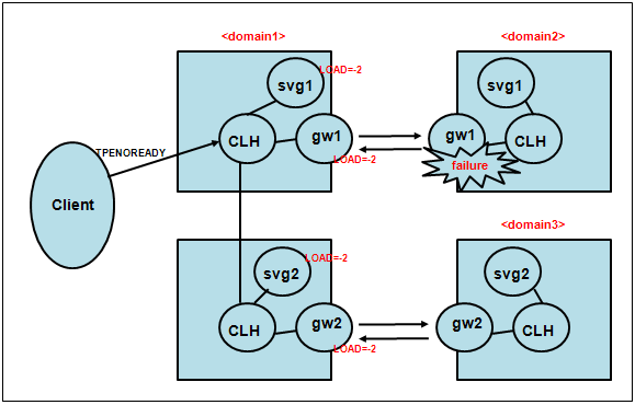
For load balancing in a multi node environment, if a server of a local node is terminated, CLH reschedules the request on a remote node. This way, client requests can be processed without errors. A CLH of a local node can issue a request to the remote node without knowing that a server on the remote node has been downed causing the client to receives a TPENOREADY error.
The intelligent routing feature (IRT) can be used to resolve such issue. It is used to manage the state of remote servers for static load balancing, and to reschedule (IRT – Intelligent Routing) the requests to other available servers. If a process of a remote node is terminated unexpectedly, it will be rescheduled to an available server.
|
The maximum number of server groups that can be rescheduled to is 10, and rescheduling is only triggered by a TPENOTREADY error. |
3.1. Existing Domain Gateway Routing
Since the existing domain gateway cannot check the state of a remote node and remote domain, it cannot detect a faulty server (including gateway) on a remote node, and can proceed with scheduling causing the client to receive a TPENOREADY error.

3.2. New Domain Gateway Routing
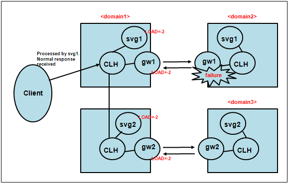
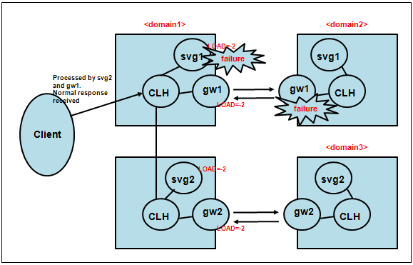
The new domain gateway checks the state of a remote node/domain to detect any remote gateway errors and route the request to another server group (svg1).

If svg1 is a dummy server group or a network failure occurs between gateways, the load is distributed to the remote nodes, svg2 and gw2, at 1:1 ratio.

4. Version-specific FD Calculation
In Tmax, FD (maximum user) calculation is different for each version. The following are the formulas for calculating the FD value for each version.
-
Tmax 5 - Tmax 5 SP1 Fix#1 b.3.5
maximum user = max_fd - maxspr - maxcpc - maxtms - maxclh - Tmax internal FD(21) - [(nodecount(The number of active nodes) - 1(own node)) * maxclh * domain.cpc] -
Tmax 5 SP1 Fix#1 b.3.7 - Tmax 5 SP2
maximum user = max_fd
              - maxspr
              - maxcpc
              - maxtms
              - maxclh
              - Tmax internal FD(21)
              - [FD connection between CLHs for multi node (maxnode(default:32) * maxclh * domain.cpc * 2)]
As for the 'max_fd' value, the smaller value between the values specified for the system and for Tmax will be used. The cpc value, 'domain.cpc', can be checked using 'cfg -d' command in tmadmin. Each setting can be checked using the cfg command in tmadmin.