Runtime Engine Server
This chapter describes the AnyLink runtime engine server’s components and architecture.
1. Server Components
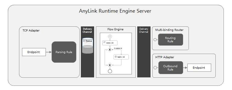
The AnyLink runtime engine server consists of a service flow engine (which determines the control flow), an adapter (which performs I/O operations for each protocol), and a multi-binding router (which handles multiple services as one).
1.1. Service Flow Engine
The service flow engine executes a service flow when triggered by receiving an event that is a message sent by other components such as an adapter.
A service flow expresses a process flow by using a diagram borrowed from BPMN (Business Process Modeling Notation). BPMN is the modeling and notation standard that represents business processes defined in OMG (Object Management Group). It is good for expressing asynchronous and concurrent processes.
A service flow is defined in a diagram format (composed of activities and events) by using Studio, and additionally provides variables, expressions, mapping, handlers, and user activity functions, in addition to the process flow.
A service flow is created by a message sent by a component such as an adapter, and can call another adaptor or a service flow or send and receive a message. Also, it supports conditional splitting, selective execution, and concurrent execution, and has a variable for storing the status for controlling flows.
The AnyLink service flow engine has a special architecture that allows it to easily run asynchronous and concurrent processes, and executes them by using thread pools allocated in the engine.
1.2. Adapter
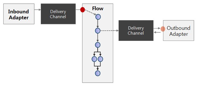
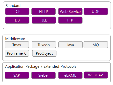
The adapter allows AnyLink to easily link with various applications, by using I/O processing through the protocol for a target application or by using a library of a target application.
The AnyLink Adapter can define two types of rules, inbound and outbound rules, depending on the direction of the I/O.
-
The inbound rule sends requests from external systems to AnyLink, and returns responses to external systems.
-
The outbound rule calls external systems from AnyLink, and receives responses.
Depending on the protocol, it may be difficult to distinguish between the request message of the inbound rule and the response message of the outbound rule. To efficiently handle this problem, AnyLink is designed to distinguish them by using a parsing rule that parses messages coming from an external system.
1.3. Multi-binding Router
The multi-binding router allows to dynamically perform routing between components at execution time. In AnyLink, a component triggers another component by sending a message.
AnyLink triggers other components by sending and receiving messages internally between components. Function names, request and response message types in a specific format, and error response message types are standardized in AnyLink as services.
AnyLink uses the following as internal services.
-
Receive Message Events
Receive message events defined by service flows receive messages from the adapter.
-
Outbound Rule
An adapter’s outbound rule receives messages from service flows.
-
Multi-binding Rule
Used to group different services together as one service. Message events of different service flows, different outbound rules of an adapter, or other multi-binding rules can be grouped together to be expressed as one service. A multi-binding rule can be used to split a group that consists of multiple services into specific services according to rules or conditions, or multi-cast to multiple services.
2. Server Architecture
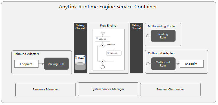
The AnyLink runtime engine server consists of two large service components which are an adapter that communicates with external systems and a service flow engine in charge of processing logic, as well as a multi-binding router service component that provides routing between various services. It also has a delivery channel for inter-component communication and rule deployment, and a resource manager.
2.1. System Architecture
This section describes the runtime engine server’s system architecture.
Runtime Engine Service Container
Runtime Engine Service Container (RTE Service Container) manages components' lifecycles as well as defines and provides services required for components. Also, it executes the service flow engine, multi-binding router, and adapter manager.
Main services provided are an internal communication channel called the delivery channel, the resource manager which manages deployment and loading of the service flow engine and adapter rules, the system resource manager which manages system resources such as thread pools and logs, and the Business ClassLoader which loads Java code used in various rules and flows.
Only one service flow engine component and multi-binding router component exist for each container, but there can be multiple adapter components for each adapter type. The adapter manager is responsible for starting and loading the adapter components. The multi-binding router component is located in the delivery channel and used to route services by using a method other than the service ID method.
Engine Architecture
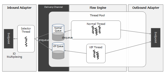
The AnyLink engine has an I/O structure which efficiently manages a large number of I/O channels, and an asynchronous process structure which minimizes waste from thread resources.
AnyLink’s main communication adapter performs I/O processing in the I/O multiplexing method, and it implements the full non-blocking processing method so that other channels' processing is not affected by buffering of a specific I/O channel. The service flow engine, which uses thread pools, is implemented as asynchronously as possible to minimize wait time. Therefore, even if multiple service flows are simultaneously executed, there is no lag from lack of thread pools.
2.2. Delivery Channel
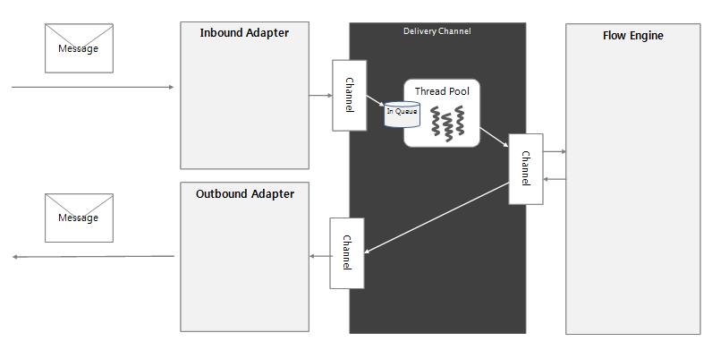
Delivery channel is a service that asynchronously supports internal communication between service components by using a pre-defined message pattern. It is the core architecture that reduces dependency between service components, and has the ability to use appropriate thread pools according to the messaging API.
-
Messaging Pattern
The delivery channel provides the following patterns of internal communication between service components.
Pattern Description Request-Response (2-way)
Sends a response message to a request message. The most common messaging pattern.
Oneway
Only sends a request message and does not wait for its response message.
Oneway-ACK
Sends an ACK message after a request message has been processed. Typically, the delivery channel guarantees the delivery and sends an ACK or a NAK message as a response.
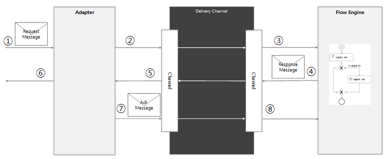
Request-Response-ACK (3-way)
Sends an ACK or a NAK message to notify whether a response message to a request message has been properly handled.
Test-Message
Inquires whether a request message can be processed. Used for correlation matching routing in multi-binding routers. For information about correlation matching, refer to "Correlation".
 Request-Response-ACK Component Communication
 -
Reliable Messaging and XA Messaging
The delivery channel selectively supports reliable messaging and XA messaging when the OneWay messaging pattern is used.
Type Description Reliable Messaging
Stores messages in a permanent storage device such as a hard disk or RDBMS, and then sends an ACK message.
XA Messaging
Supports global transactions. Usually used to send multiple messages when global transactions are in progress in the Tmax adapter. Multiple messages grouped in a single transaction can be batch processed because global transaction messages such as prepare, commit, and rollback through 2-phase commit by using the Tmax adapter.
-
Transaction Propagation
The delivery channel starts or ends transactions depending on the message properties, or propagates the transaction context. Also, it can manage global transactions' XA resources.
The delivery channel provides functions that can participate in transactions by receiving the transaction context of the message sent from a transaction manager such as Tmax or JEUS. As a transaction manager, it can also start transactions internally in AnyLink and propagate global transactions to XA resource managers such as external RDBMSs, or JEUS and Tmax. Each transaction’s configuration can be set by using properties of a service flow or adapter rule.
2.3. Runtime Engine Service
The runtime engine service container provides services required for runtime execution in addition to the delivery channel.
-
Resource Manager
Manages various rules, resources, and Java code contained in transactions and transaction groups of businesses that are internally defined.
-
System Resource Manager
Manages the thread pools and system logging used by the runtime engine.
-
Business Class Loader
Java code classloader that implements dependency processing such as the hierarchical structure of Java code and major resources, as well as the symbolic link.
-
Deploy Manager
Dynamically and reliably deploys various resources received from the data integration server (DIS) through 2-phase deployment. If resources are undeployed or redeployed, then the existing resource files are moved to the backup directory, and either deleted or updated. If the runtime engine’s deploy service generates an error in the first phase (prepare) of deployment, then the DIS rolls back the deployment to all servers.
3. Runtime Engine Error Processing
AnyLink provides a method for dealing with errors in various situations. Depending on the level in which an error is generated, the terms as well as error handling are different. This section briefly describes how to handle the errors that occur in the runtime engine.
3.1. Delivery Channel
There are instances where an error occurs when a message is sent from a service component to another service component from the delivery channel, which is a communication channel between service components inside the AnyLink runtime engine. This is an internal system error, so AnyLink users do not have to concern themselves of it, but it does help users to understand the internal operation of AnyLink.
The delivery channel that is responsible for communication between service components internally in the engine can distinguish between responses to requests and error responses. The delivery channel’s error response is used to send an error as a response when an internal error occurs while handling a message in the service component.
The delivery channel’s error response is different from abnormal responses from the business perspective. Abnormal responses from the business perspective must be sent via response messages, same as normal responses. Hence, when service components send abnormal response messages, they use the same APIs as the normal response messages in the delivery channel, and use a separate API to send an error.
3.2. Service Flow
The AnyLink service flow internally defines error events, error handlers, and error code mappers. Also, it defines mechanisms for handling abnormal responses for service requests.
-
Error Events
The AnyLink service flow generates (when using an error event as the last event) or detects (when using an error event as a boundary event) error events for controlling flows.
Error codes are used for throwing or receiving error events. When an unexpected error (a Java exception) occurs during the execution of a service flow instance, the error code mapper converts the error to an error code. Hence, the error code mapper is an interface that converts a Java exception to an error code in which a service flow can recognize. By default, the error code mapper is not defined. However, for an exception that is not converted to an error code, the exception object’s entire class name is used as the error code. An error code can be specified to handle an error by using a boundary event. If ALL is specified, all errors can be handled regardless of the exception type or error code value.
-
Error Handlers
There is a process error handler which is specified for each service flow, and an activity error handler which is specified for each activity. When an exception occurs during the execution of a service flow instance, if a process or an activity error handler is specified, then the service flow can be normally executed because the error handler handles the error.
-
Service Activity’s Abnormal Responses
An abnormal response can be received when a service such as an adapter outbound rule or multi-binding router rule is invoked. An abnormal response is contextually defined on the side that sends the abnormal response. When an abnormal response occurs, mapping for the abnormal response can be separately specified.
Take caution in that if an abnormal response mapping or abnormal response parameter is not specified in the activity when a service sends an abnormal response, then instead of using a response mapping or response parameter, an abnormal response message is not stored in a parameter.
An abnormal response in an AnyLink service flow has nothing to do with an error event. Hence, the abnormal response is not related to the flow control method that handles errors in the service flow.
3.3. Adapter
Adapters define abnormal response messages in addition to response messages in the parsing rules. As well, an adapter can define system error messages when internal system errors occur in the adapter’s endpoint.
Adapters define request messages and response messages as well as abnormal response messages in the parsing and outbound rules. As well, an adapter has rules designed for specifying responses for various error scenarios such as system errors and format errors. For more information about how each adapter handles errors, refer to the relevant adapter guide.