EMB Designer
This chapter describes EMB Designer’s characteristics, components, and relevant information.
1. Overview
EMB Designer is a GUI tool that implements ProFrame’s EMB technology. It is used to create service and application modules. It is embedded in Studio. It allows to create application modules and develop a new service by assembling multiple modules without coding. For information about how to create EMB modules, refer to Starting EMB.
2. Characteristics
EMB Designer has the following characteristics.
-
Visualizes service business logic.
-
Service design and development
-
Applications and workflows
-
Complex integrated services
-
Service assembling and disassembling
-
Easy service implementation
-
-
Minimizes dependency between applications.
-
Makes application logic as assets.
-
Increases resource reusability.
-
Model Driven Architecture (MDA)
Visually models business logic and converts it into executable source to implement MDA.
Category Description Source Generation Engine
A service flow created with EMB Designer is converted into actually available skeleton code by Source Generation Engine.
C Skeleton Code
C skeleton code is C code that sequentially and structurally implements workflow by calling source code converted through Source Generation Engine as a static function. In other words, C skeleton code includes code progression according to the order of flow, function calls, and function definitions. A developer can rapidly complete a module that handles a unit task by adding some code to the skeleton code. This kind of modules are combined and become a service module that can be externally called.
The following describes the benefits of using EMB Designer for each role.
| Role | Description |
|---|---|
Designer |
Efficiently designs service logic flow. |
Worker |
Intuitively understands the workflow. |
Developer |
Shortens development time and develops logical services by adding necessary code to Skeleton Code created for each workflow. |
3. Components
EMB Designer can be integrated with not only modules created in Studio but also various resources created in another TmaxSoft system such as ProFactory, ProRule, and ProBus. You can create a service’s business logic flow by dragging and dropping the modules.
The following modules can be created in EMB Designer.
-
Service module
Includes other modules as a top-level ProFrame module like a batch module. While submodules are not exposed to outside as a service, this module consists of a transaction that is exposed to outside and has a transaction code used for calling.
Business and DBIO modules can only be accessed by calling from a service module.
In EMB Designer, a service module allows to create a new service by combining and placing submodules and other modules that are saved in ProFrame’s Resource Pool as business logic.
-
Business module
Actual service contents. Used by calling from a service module. A business module is distinguished with implementation complexity, usage, manageability, and runtime performance, but the most important thing is reusability. The key successful factor of using EMB is extracting and reusing a repeated and common part as a business module.
-
Pre-processing module
Application pre-processing module. You can create with the same method as for business modules. Create this module if there is a common job before a service module call. If not, use a service module.
-
Post-processing module
Application post-processing module. You can create with the same method as for business modules. Create this module if there is a common job after a service module call. If not, use a service module.
-
DBIO module
ProFrame provides all functions to access a database separately from an application. All the functions are defined in a separate development environment, DBIO Editor of Studio, and used by other modules through abstract API.
-
Template module
Create repeated jobs for each application and common business logic flow as a template. You can use this template when creating an actual module.
-
Batch module
Used for large volume of batch jobs. Exposed to outside as a service. Batch code is required to call this module.
4. Environment Configuration
The following describes preferences about Design Editor and Source Editor that are required to use EMB Designer embedded in Studio.
4.1. Design Editor
The following describes how to check and set preferences about Design Editor in Studio.
-
Select [Window] from the main menu and then select [Preferences] > [ProFrame] > [Design Editor].
-
In the open dialog box, set desired items and click [OK].
To apply changes without closing the dialog box, click [Apply]. To restore the default settings, click [Restore Defaults].
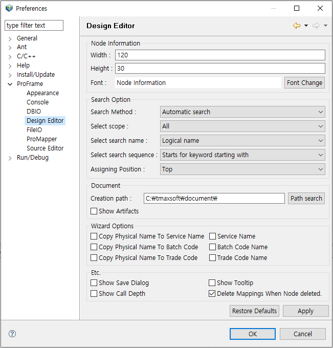 Studio – Design Editor Preferences
-
Node Information
Settings about nodes in flow diagrams.
Item Description Width
Width of a node.
Height
Height of a node.
Font
Font of text expressed in a node.
-
Search Option
Settings used when searching for a specific module from Resource Pool View.
Item Description Search Method
Search method.
-
Automatic search: Displays search results after a few seconds after entering a search word.
-
Search Manually: Displays search results after entering a search word and clicking [Search].
Select scope
Search scope (either All or User).
Select search name
Either logical or physical name used to search for resources.
-
Logical name
-
Physical name
Select search sequence
Location of a search word.
-
Starts for keyword starting with: Searches for items from the start word.
-
Keyword containing: Searches for items including entered word.
Assigning Position
Position where items are added (either Top or Bottom).
-
-
Document
Settings about output created when selecting [Export To Document] in EMB Designer.
Item Description Creation path
Path where output is saved.
Clicking [Path search] can specify a path in a developer’s local computer.
Show Artifacts
Option to create output.
-
Wizard Options
Settings about options used in the Create a new Service Module dialog box. Copy Physical Name To Service Name Copy Physical Name To Batch Code Copy Physical Name To Trade Code Service Name: Changed to uppercase. Bach Code Name: Changed to uppercase. Trade Code Name: Changed to uppercase.
-
Etc.
Item Description Show Save Dialog
Shows a window with a notification message after save.
Show Tooltip
Shows a tooltip about a node when you hover the mouse over the node.
Show Call Depth
Shows the number of calls of a Call module. The number in red is displayed at the top right of the module’s node.
Delete Mappings When Node deleted.
Permanently deletes relevant mapping information from a database when deleting a mapped Call module.
-
4.2. Source Editor
The following describes how to check and set preferences about Source Editor in Studio.
-
Select [Window] from the main menu and then select [Preferences] > [ProFrame] > [Source Editor].
-
In the open dialog box, set desired items and click [OK].
To apply changes without closing the dialog box, click [Apply]. To restore the default settings, click [Restore Defaults].
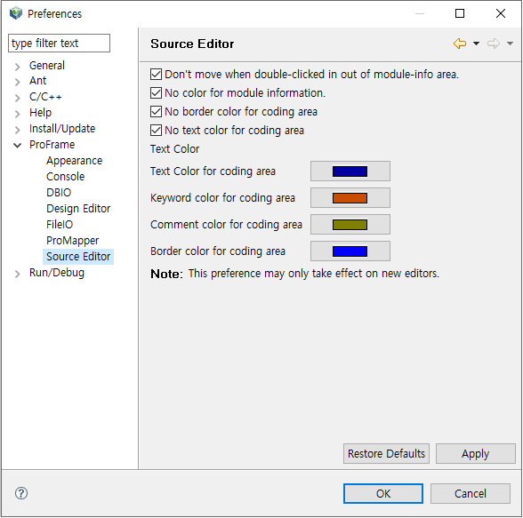 Studio – Source Editor Preferences
Item Description Don’t move when double-clicked in out of module-info area.
Module information comments mean comments automatically created in Source Editor when creating an EMB module. The comments start with /**** and end with ****/. Double-clicking a module information comment goes to the corresponding node in module editor.
If cleared, double-clicking any point in Source Editor goes to a node in the corresponding coding area.
No color for module information.
If cleared, a square box and color is displayed around the module information comment.
No border color for coding area
If cleared, the set color is applied to lines that start with "//DO_NOT_MODIFY_THIS_LINE…" for readability.
No text color for coding area
If cleared, color for text code in the coding area is changed to the color set with the submenu.
Text color
Color for each item when check boxes above this check box are cleared.
-
Text color for coding area
-
Keyword color for coding area
-
Commend color for coding area
-
Border color for coding area
If all the check boxes are cleared, the Source Editor page is as follows:
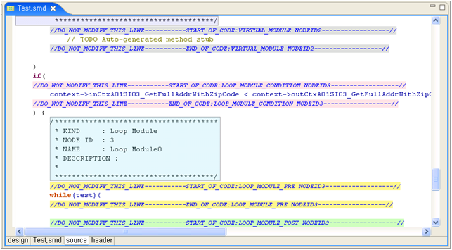 Sample Source Editor Page
 -
5. Screen Layout
In EMB Designer, you can assemble and disassemble modules such as service, business, and DBIO modules and also designs EMB modules by using various auxiliary tools.
The screen consists of the following three main areas (①~③) and one auxiliary area (④).
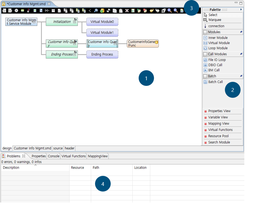
① Module editor
② Palette
③ Toolbox
④ Views
Module editor
In this area, you can create a flow diagram of an EMB module and design a service or application flow by selecting various resources from Palette (②).
-
Components
The module editor provides the following four tabs at the bottom left.
Tab Description design
Design Editor allows to create a service or application flow. This tab is useful for EMB module creation because it visually shows sub or application flows.
{physical_name}.smd
Meta Editor shows XML information of an EMB module, where XML is a meta file used in ProFrame.
Meta files' extension varies depending on the resource modules.
-
Service module: {physical_name}.smd
-
Business module: {physical_name}.md
-
Batch module: {physical_name}.btm
source
Source Editor shows source of a module created in Design Editor.
header
Header Viewer shows contents of header files of a created EMB module.
-
Palette
This area lists diagrams and resources that can be used to create a service or application flow. It has functions that can be used to create a flow diagram in Module Editor. However, when opening a RI resource, editing functions (Modules, Call Modules, and Batch) are hidden and only views are shown. The functions for searching and calling resources are only for RI area resources.
| Function | Description | |
|---|---|---|
Select |
Used to select one node. |
|
Marquee |
Used to select multiple nodes. |
|
connection |
Used to connect or reconnect nodes. |
|
Modules |
Inner Module |
Used to insert an inner module to service or application flow diagram. |
Virtual Module |
Used to insert a virtual module to service or application flow diagram. |
|
Loop Module |
Used to insert a loop module to service or application flow diagram. |
|
Call Modules |
File IO Loop |
Used to insert a FileIO module to service or application flow diagram. Available only when FileIO Plugin is installed. |
DBIO Call |
Used to insert a DBIO module to service or application flow diagram. |
|
BM Call |
Used to insert a business module to service or application flow diagram. |
|
Batch |
Tx Begin |
Used to process TX Begin. Shown only for Batch Editor. |
Tx Commit |
Used to process TX Commit. Shown only for Batch Editor. |
|
Tx Rollback |
Used to process TX Rollback. Shown only for Batch Editor. |
|
DB Commit |
Used to process DB Commit. Shown only for Batch Editor. |
|
DB Rollback |
Used to process DB Rollback. Shown only for Batch Editor. |
|
Batch Call |
Used to insert a batch module to service or application flow diagram. |
|
Properties View |
Used to check or set properties of a selected module. |
|
Variable View |
Shows lists of variables used in modules. |
|
Mapping View |
Shows lists of mappings used in modules. |
|
Virtual Functions |
Used to create a general function with developer-defined parameters and use it in a service or application flow diagram. |
|
Resource Pool |
Used to search for resources. |
|
Search Module |
Used to search for call modules used in modules. |
|
Toolbox
This area provides icons of functions that are frequently used to create service or application flows.
The following describes each icon.
| Icon | Description |
|---|---|
|
Opens a dialog box that sets and changes a module’s input structure. Enabled when selecting top-level start node. |
|
Opens a dialog box that sets and changes a module’s output structure. Enabled when selecting top-level start node. |
|
Sets a selected node’s exception handling. Enabled when selecting a start or Inner node. |
|
Opens a dialog box that defines CommBuff. Enabled when clicking the Module Editor area. |
|
Opens a dialog box that defines constants. Enabled when clicking the Module Editor area. |
|
Opens a dialog box that defines contexts. Enabled when clicking the Module Editor area. |
|
Opens a dialog box that defines structures. Enabled when clicking the Module Editor area. |
|
Opens a dialog box that defines local variables. Enabled when selecting a start or Inner node. |
|
Opens a dialog box that sets loop pre and post-processing. Enabled when selecting a Loop module. |
|
Opens a dialog box that writes code to insert to a source file. Enabled when selecting a Virtual module. |
|
Opens a dialog box that sets input mapping of a Call module. Enabled when selecting a Call module. (Not supported in the current version. Only bypass is available) |
|
Opens a dialog box that sets input mapping of a module that currently opens in the editor. Enabled when selecting a space other than another module in EMB. (Not supported in the current version.) |
|
Opens a dialog box that sets output mapping of a Call module. Enabled when selecting a Call module. (Not supported in the current version. Only bypass is available) |
|
Opens a dialog box that sets output mapping of a module that currently opens in the editor. Enabled when selecting a space other than another module in EMB. (Not supported in the current version.) |
|
Enabled when selecting multiple modules that have the same parent node. Used to set and cancel the XOR setting for these modules. |
|
Checks source. Enabled when clicking the Module Editor area. |
|
Used to add a Fetch execution node. Enabled when selecting a DBIO module. |
|
Used to reconfigure a module. Enabled when selecting a Call module. |
|
Copies a selected node to clipboard. |
|
Pastes a copied node under a selected node. |
|
Deletes a selected node. |
|
Executes a unit test for a selected module. |
|
Starts log view. |
|
Stops log view. |
|
Executes undo. |
|
Executes redo. |
|
Shows all the subnodes of a Call module. The subnodes cannot be edited because they are read-only in Module Editor. |
|
Expands the Module Editor area. |
|
Collapses the Module Editor area. |
|
Executes source creation. Enabled when clicking the Module Editor area. |


Views
This area shows detailed information about EMB modules, mapping information between modules, registered resources, etc. For example, you can check virtual functions, variables, and resource pools.
|
The following only describes the Properties view. For information about other views required to create EMB modules, refer to Creating a Flow. For information about each module, refer to Unit Test. |
Properties view is used to check or reset properties of a created EMB module.
To display the Properties view, click Properties View in Palette or select [Window] > [Show View] > [Properties] in Studio.
The following describes each property in the Properties view for service modules.
| Property | Description | |
|---|---|---|
Build |
Makefile |
Creates and saves Makefile to use when building a service module through the Makefile edit dialog box. |
ComBuf |
Commbuf |
Opens the Define CommBuff dialog box that sets CommBuff variables. |
Constant |
Constant |
Opens the Define constant dialog box that sets constants. |
Context |
Context |
Opens the Define context dialog box that sets contexts. |
Header |
Include header |
Opens the Include header edit dialog box that additionally sets header files. Enter header files to add in the dialog box. |
Post Processing |
Post process input mapping |
Sets input mapping between a post-processing module and a selected service module. |
Post process module |
Searches and sets post-processing modules. |
|
Post process output mapping |
Sets output mapping between a post-processing module and a selected service module. |
|
Pre Processing |
Pre process input mapping |
Sets input mapping between a pre-processing module and a selected service module. |
Pre process module |
Searches and sets pre-processing modules. |
|
Pre process output mapping |
Sets output mapping between a pre-processing module and a selected service module. |
|