Creating an Online Program
Online programs are created in the form of service modules in ProFrame. This chapter describes how to create a service module.
1. Procedure for Creating Service Module
Set the service module name and register the same name for the service in TP-Monitor to create a service module.
The following is the procedure to create a service module.
-
Create an input/output structure
-
Implementation for service module
-
Compile and Hot Deploy
-
Unit test and debugging
2. Creating an Input/Output Structure
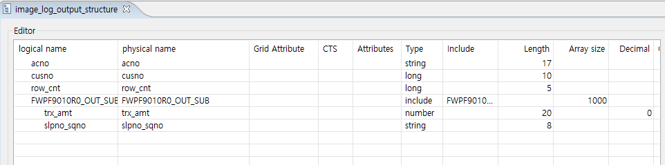
Create the structure for the data format of the input/output message to create the input/output structure of the service module.
Input/Output Structure Definition
After creating an I/O structure, the macro of the input/output structure defined as follows id displayed in the source editor of EMB Designer.
#define INPUT    (context->input)
#define OUTPUT   (context->output)
Since the macro is defined in the header file of the generated service module, it can be used as INPUT→grid[0].name in the program.
If there is a structure included in the figure above, compile the structure first and then Dludpate. If the structure is changed (when structure members are added, deleted, or the length is changed), you must re-create the message, compile and Dlupdate it. In other words, when the structure is changed, all programs that use the structure must be compiled and Dlupdate.
|
For more on the structure creation, refer to ProFrame ProMapper Developer Guide. |
-
Restrictions of I/O structure
For smooth communication with the terminal, sub-structures are included up to level 1 only. The structures must not include other structures. In the case of an array, you need to prepare an item that can designate the number of data for variable processing.
-
Compile of I/O structure
The I/O structure of the service module needs compile for message communication. Included sub-structures do not need to be compiled separately, and only I/O structures that are directly used are compiled and updated. At this time, compiled file is not the header file of the structure, but the ~MsgFld.c file, which is a message conversion source generated one for each structure.
Message Creation
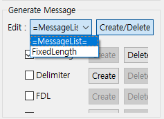
The structure registered in the service module needs to create the message after saving.
To create a message, select a text type such as FixedLength on the text creation screen of the ProMapper editor, edit the text according to the selected text type, and save it. To convert messages coming from various channels into structures, you need to compile the structures and run Dlupdate.
|
For details on message creation, refer to ProFrame ProMapper Developer Guide. |
-
Specifying the message length of a numeric type
After creating the structure, execute the message edit dialog box to designate the field length by +1 for numbers and +2 for numbers with decimal points. This is to secure the length including the sign.
3. Service Module Implementation
Right-click on the workspace navigator and select [New] > [EMB Design] to create a service module.
3.1. Creating New Service Module
Following dialog box of new service module creation is displayed .
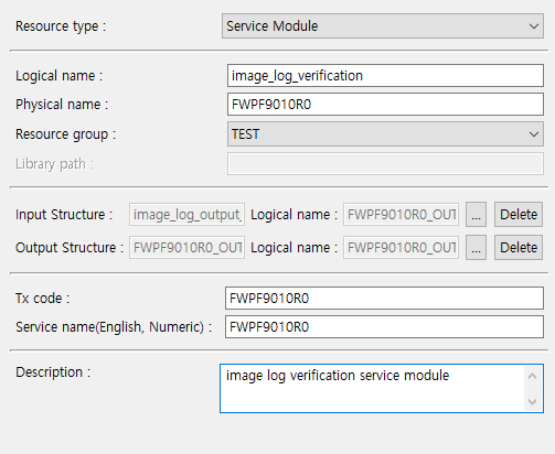
The following is a description of each item in the dialog box.
| Item | Description |
|---|---|
Resource type |
Set the type of module to be created. Here, select 'Service Module'. |
Logical name |
Do not use special characters (space characters, {, }, \, etc.). |
Physical name |
Do not use special characters (space characters, {, }, \, etc.). |
Resource group |
Set the resource group that contains the service module to be created. |
Library path |
Set the library path referenced by the service module to be created. |
Tx code |
It is required fields and must be entered in uppercase letters. Set the parameter key value that defines the business characteristics of the service module. |
Service name(English, Numeric) |
It is required fields and must be entered in uppercase letters. Set the service name of TP-Monitor to be registered as a service module. |
3.2. Using EMB Designer
If basic information required for service module creation is registered in the previous section, EMB Designer that can create service module is displayed as follows:
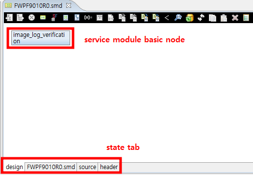
EMB Designer has the most basic node for creating service modules. Starting with the basic node, create a service flow by connecting previously created modules. EMB module is created based on GUI. You can design the work flow of the service module by dragging and dropping the previously created resource to EMB Designer or using the [Palette].
|
For details on EMB Designer, refer to ProFrame EMB Developer Guide. |
The following describes how to place a resource module in EMB Designer.
-
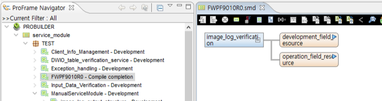
Navigator Area
Navigator has a Proframe Navigator that can check operating area resources and a workspace navigator that can check work area resources. Select a resource based on the provider in each navigator and place it by dragging and dropping it to the location of the node to connect to the module editor of EMB Designer. At this time, the resource module moves automatically depending on the location of the node to be inserted, and if you drag and drop the module in ProFrame Navigator, it refers to the operating area resource, and if you drag and drop it in the workspace navigator, it refers to the resource in the work area.
Resources in the workspace can be easily identified by displaying 'WS -' in the module name text.
 EMB Designer
 -
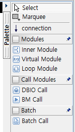
[Palette] Menu
Select the module to be placed in [Palette]. In the menu, there is a function to connect or select a module and a module.
 Palette Menu
Menu Description Select
Selects a resource or module placed in EMB Designer.
Marquee
Selects multiple modules.
connection
Connects resources and modules to represent business process flow.
Inner Module
Sets variables used by multiple modules at the same time, or sets entry conditions and exception handling of modules.
Virtual Module
Inserts simple coding without input/output into the work flow.
Loop Module
Repeatedly executes the multiple modules.
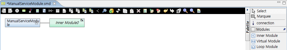
3.3. Using IM, VM, LM
The method to insert modules such as IM (Inner Module), VM (Virtual Module), and LM (Loop Module) in [Palette] is as follows:
After selecting the module to be inserted, move to the location to be placed in the module editor of EMB Designer.
-
Loop pre- and post-processing
In the case of LM, unlike other modules, pre- and post-processing for loop must be performed. Pre- and post-processing records the contents of which command to repeat, how many times to repeat, and when to exit the loop.
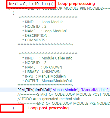 Loop Pre- and Post-processing for LM
 -
Entry condition
Each module can be executed only in specific cases by setting entry conditions. To set the entry condition, select [Condition] from the menu that appears when you right-click on the module you want to set.
When the Condition dialog box appears, enter the entry condition in the entry condition text box. In this case, the input method is created by direct input or by combining the variable and operator at the bottom of the entry condition dialog box screen.
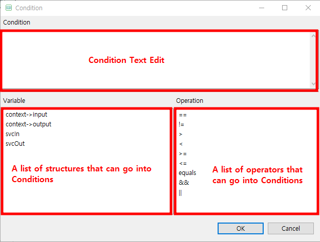 Dialog Box of Entry Condition
When all entry conditions are created, the following source code is generated.
If(context->input->item > 0) {
/*********************
* KIND: Intermediary Module Function Call
* NODE ID: 1
* NAME: Inner Module
* COMMENTS:
**********************/
PFM_TRY(innerModule(context));
}
4. Compile, Dlupdate
When the service module implementation is completed, click [Compile] to compile the sources and click [Dlupdate] to execute Hot Deploy in the studio.
Compile and Dlupdate for the module are required to operate the service module normally and the same in the created I/O structure.
5. Unit Test and Debugging
If the results of compile and Hot Deploy are normal, unit tests are performed using the test framework. The way to run unit tests is to run the unit test function built into the studio.
|
For details on unit test, refer to ProFrame Unit Test Guide. |
If an error occurs in the service module after the unit test, it is solved through the debugging process. Here, debugging is the process of verifying the process of creating a service module.