Starting EMB
This chapter describes how to create EMB modules in EMB Designer.
|
This guide assumes that EMB modules are created in Studio. |
1. Overview
This chapter describes the following for EMB module creation.
-
Adding module’s basic information
Add basic information about an EMB module to create in Studio. For detailed information, refer to Adding Module’s Basic Information.
-
Creating a flow
Create a service or application flow diagram based on added basic information in EMB Designer. For detailed information, refer to Creating a Flow.
-
Editing a flow
Edit a service or application flow diagram in EMB Designer. For detailed information, refer to Editing a Flow.
-
Compilation and Dlupdate
Compile a written EMB module and execute Dlupdate to create the module. For detailed information, refer to Compilation and Dlupdate.
-
Unit Test
Perform a unit test to check whether a created EMB module operates normally. For detailed information, refer to Unit Test.
2. Adding Module’s Basic Information
The following are the steps for adding basic information.
-
Select [New] > [EMB Design] from the context menu of Workspace Navigator.
-
The following Create a new Service Module opens. In this dialog box, basic information required to create an EMB module can be added.
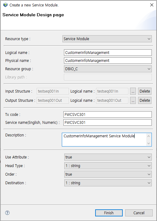 Create a new Service Module
The following describes each item.
Item Description Resource type
Resource type of an EMB module to create.
Logical name
Logical resource name of an EMB module to create.
Physical name
Physical resource name of an EMB module to create.
Resource group
Resource group of an EMB module to create.
Resource groups categorize resources for easy development. Only resource groups that are registered in WebAdmin are displayed. If a desired resource group does not exist, add the resource group in WebAdmin. To add a resource group, log in to WebAdmin and select [META SYSTEM] from the main screen and then select [META SYSTEM] > [ResourceGroupMgmt]. In the ResourceGroupMgmt screen, check currently set resource groups and then register the resource group to add.
Input Structure
Input structure of an EMB module to create. Only workspace structures are available.
Output Structure
Otuput structure of an EMB module to create. Only workspace structures are available.
Tx code
Code used as a key value required to externally call a service module. This is available only when Resource type is set to Service Module.
Service name (English, Numeric)
Service name registered in Tmax server. Enter a logical name that can be identified when registering a service module. This is available only when Resource type is set to Service Module.
Description
Description about a resource of an EMB module to create.
The following are the steps for specifying Input and Output Structures in the Create a new Service Module dialog box.
-
Click […].
-
The Select Input & Output Structures dialog box is displayed.
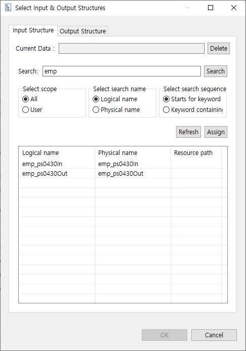 Select Input & Output Structures – Input Structure
 -
In the [Input Structure] tab, enter an input structure to search and then click [Search].
-
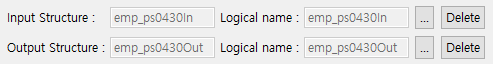
Double-click a desired input structure from the search results. This displays 'logical name [physical name]' of the selected input structure in 'Current Data'. To select another input structure, click [Delete].
-
After selecting an input structure, click [Output Structure] tab. Enter an output structure to search and then click [Search].
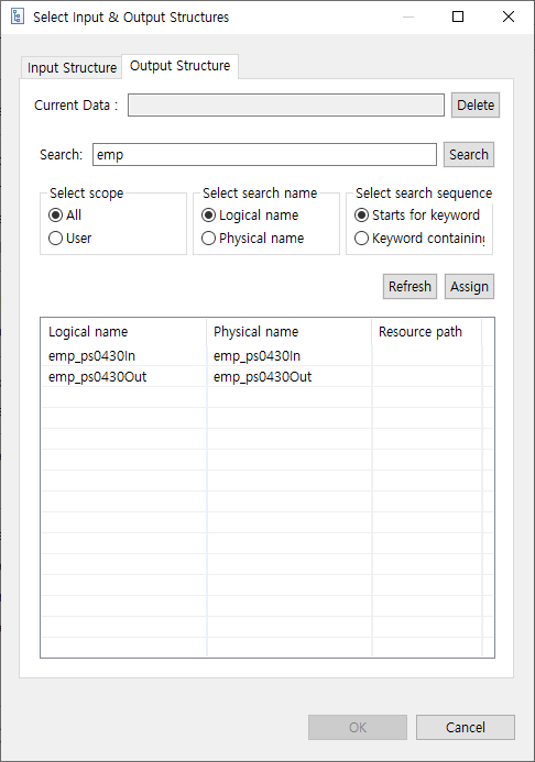 Select Input & Output Structures – Output Structure
 -
Selecting both input and output structures enables [OK]. The Select Input & Output Structures dialog box is closed. The selected input and output structures' names and logical names are displayed in the Create a new Service Module dialog box. To delete a specified input or output structure, click [Delete] next to the logical name.
-
-
After setting all basic information about the module, click [Finish] to go to the screen where you can design an EMB module.
3. Creating a Flow
Create a flow in EMB Designer by designing an EMB module based on the added basic information.
The following describes how to design a flow diagram of an EMB module by using Module Editor and Palette. Additionally, it describes how to design it by using a Call module that is an external module added to Navigator area and a resource pool (RI resource).
3.1. Module Editor
The following describes each component of Module Editor in the order of tab arrangement.
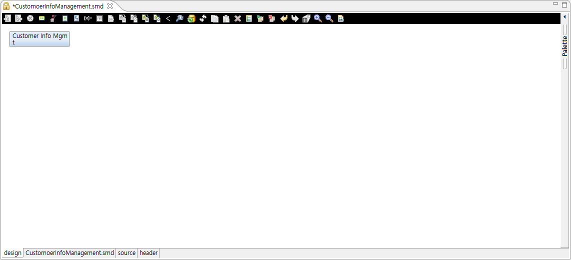
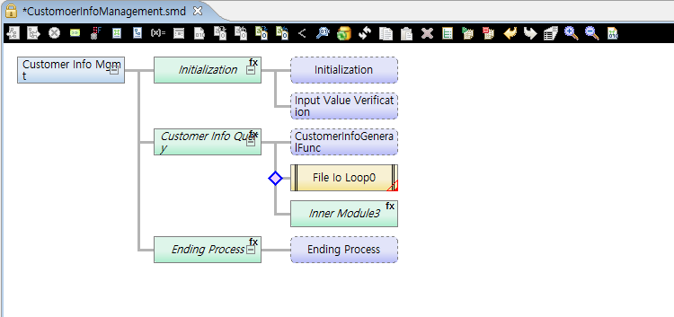
Design Editor
Initial screen displayed after adding module’s basic information. It visually shows EMB module flows.
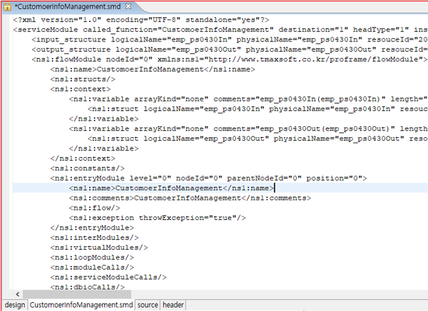
Meta Editor
Shows XML information of an EMB module.
Source Editor
Shows module source.
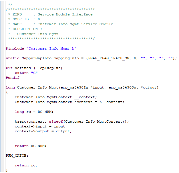
The following describes a part of source in Example of Meta Editor.
① long CustomerInfoManagement(test_dept_qpstest_p_s2In *input,
test_dept_qpstest_p_s2Out *output)
{
    CustomerInfoManagementContext __context;
②  CustomerInfoManagementContext *context = &__context;

③  long rc = RC_NRM;

    bzero(context, sizeof(CustomerInfoManagementContext));
    context->input = input;
    context->output = output;

    return RC_NRM;

PFM_CATCH:
    return rc;
}
The following describes the previous source.
① The physical name (CustomerInfoManagement), added in Adding Module’s Basic Information, is created as a function name that can be externally called. Also, input structures are set as parameters (test_dept_qpstest_p_s2In *input, test_dept_qpstest_p_s2Out *output).
② The context structure (*context) includes all input and output structures used by a created module.
③ The return value (RC_NRM) is defined to inform whether the function execution is successful or not in the source.
Header File Viewer
Shows contents of header files of an automatically created module.
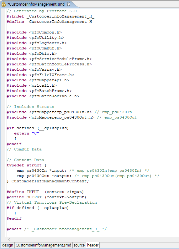
The following describes a part of source in Example of Header File Viewer.
// Context Data
① typedef struct {
    test_dept_qpstest_p_s2In *input;
/* test_dept_qpstest_p_s2In(test_dept_qpstest_p_s2In) */
    test_dept_qpstest_p_s2Out *output;
/* test_dept_qpstest_p_s2Out(test_dept_qpstest_p_s2Out) */
} CustomerInfoManagementContext;

② #define INPUT  (context->input)
③ #define OUTPUT (context->output)
The following describes the previous source.
① Sets the context structure defined in Source Editor.
② Automatically defines input macro for easy coding.
③ Automatically defines output macro for easy coding.
To additionally add header files, use the header file creation function provided by ProFrame.
The following are the steps for creating a header file.
-
Select [New] > [Header] from the context menu of Workspace Navigator.
-
The following New Header Project Creation opens.
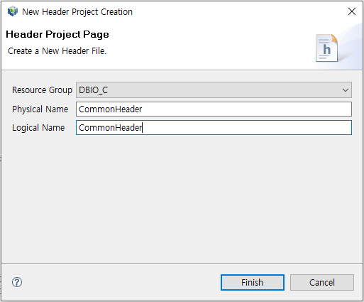 New Header Project Creation
Item Description Resource Group
Resource group of the header file.
Physical Name
Physical name of the header file.
Logical Name
Logical name of the header file.
-
Enter required information and then click [Finish]. This opens header source page where you can edit the created header file.
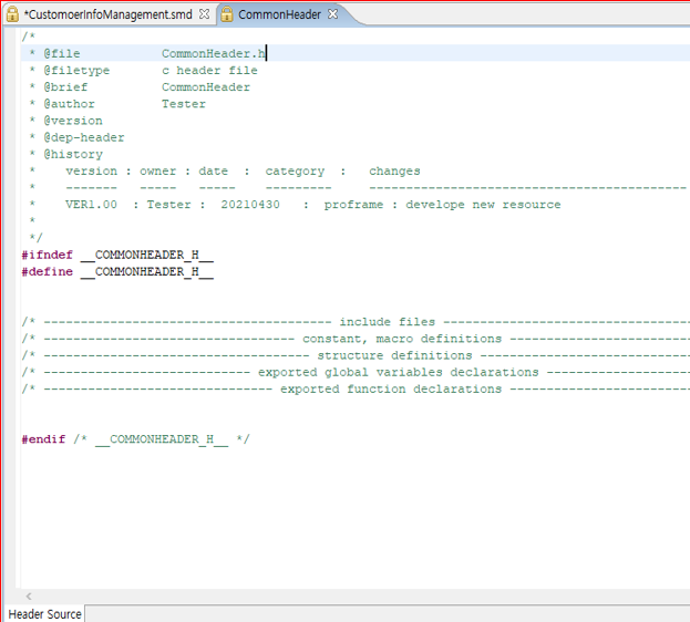 Header Source Page
The created header file can be used in an EMB module.
3.2. Palette
Palette has diagrams and resources that can be used to create a flow. Various nodes can be created for flow diagram creation, and the nodes can be selected and connected each other.
To create a flow diagram, it is necessary to understand diagrams and nodes that compose a diagram. The following describes each diagram and node.
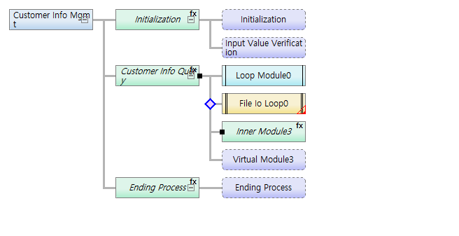
Flow Diagram
A flow diagram defines an application flow of a created EMB module and designs node relationships. It shows properties and data of each node as icons and figures for easy flow creation.
-
Node
The following are general modules in Modules.
Module Node Inner module
Virtual module
Loop module
To display a node in Design Editor, select a module from Modules and place it in a desired position.
The following are nodes displayed depending on the resource module selected in Navigator.
Provider Resource Module Node PROBUILDER
biz_module
batch_module

PROBUILDER
service_module
DBIO
persist
view
execsql
dynamicsql

To display a node in Design Editor, select a resource module from Navigator and drag and drop it to a desired position.
-
Node property
Each node in a flow diagram has properties. Displayed icons are different depending on the properties.
Property Icon Description Module

Handles an exception when included in the Exception-Catch clause.

Expressed as a function call if the Inner module is the Function type.

The If condition statements is inserted at the entry point of the code area.
DBIO Module

Persist (Used for UPDATE and INSERT)

View (Used for SELECT)

ExecSQL (Used by selecting a defined query at runtime)

DynamicSQL (Used by dynamically creating a query at runtime)

Fetch (Used for multiple data manipulation)
I/O Mapping
In Business, Batch, and DBIO modules, input and output structures are connected through mapping. They also send and receive parameters through mapping. Icons that display their status are different depending on the mapping method (Bypass, Transformation).

Bypass for input structures.
(Displayed when the created EMB module’s input structure is the same as that of the module called in the EMB module. Therefore, since the input structures used as parameters between modules are the same, data is passed as it is.)

Bypass for output structure.
(Displayed when the created EMB module’s output structure is the same as that of the module called in the EMB module. Therefore, since the output structures used as parameters between modules are the same, data is passed as it is.)

Transformation for input structures.
(Displayed when changing and inputting converted data if the created EMB module’s input structure is not the same as that of the module called in the EMB module.)

Transformation for output structure.
(Displayed when changing and inputting converted data if the created EMB module’s output structure is not the same as that of the module called in the EMB module.)
-
Node status
Each node in a flow diagram shows status with a different form.
Status Node Description Inner Module Exception

Handles an exception by calling a static function and adding a Catch statement to an Inner module source.
Catch Exception

Handles an exception by calling a static function and adding a Catch statement to a Business, Batch, or DBIO module source.
Disabled

Displayed in a flow diagram, but there is no actual source in Source Editor.
-
Various expressions of a flow diagram
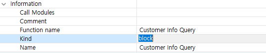
A flow diagram is expressed differently depending on module properties and settings. To check the properties, click [Properties View] in Palette to display the properties view at the bottom of EMB Designer. ** Inner module
+
Diagram Description 
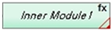
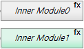
Displayed when inserting an Inner module.
This diagram is displayed when the 'Kind' property in the properties view is set to 'function'.
Displayed when exception handling is set in an Inner module.
This diagram is displayed when the 'Ignore exception flag' property in the Exception section of the properties view is set to 'true'.
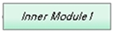
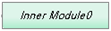
This diagram is displayed when the 'Kind' property in the properties view is set to 'block'.
-
Virtual module
Diagram Description 
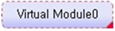
Displayed when inserting a Virtual module.
Displayed when exception handling is set in a Virtual module.
-
DBIO module
For information about DBIO, refer to ProFrame DBIO Developer Guide.
Diagram Description 
Displayed when inserting a DBIO module of the Persist query type.

Displayed when inserting a DBIO module of the View query type.

Displayed when inserting a DBIO module of the ExecSQL query type.
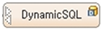
Displayed when inserting a DBIO module of the DynamicSQL query type.
Displayed when inserting a DBIO module of the Fetch Exec query type.
The following is a diagram related to a Lock query.
Diagram Description 
Displayed when a Lock query is set.
The following are diagrams for each resource.
Diagram Description 
Service module

Business module
Exception module

Batch module

FileIO module
The following are diagrams for each I/O mapping.
Diagram Mapping Method Description 
I/O Bypass mapping
Passes a structure used as an input/output parameter for reference.
Before Code mapping
Manually write code related to input mapping.
After Code mapping
Manually write code related to output mapping.
-
3.2.1. General Modules
The following describes each general module in Modules of Palette.
| Module | Description |
|---|---|
Inner Module |
Called as a static function in source. Controls or supports the flow between business modules through functions such as inserting exception handling statements in the function call part, using local variables in the function implementation part, and inserting conditional statements. |
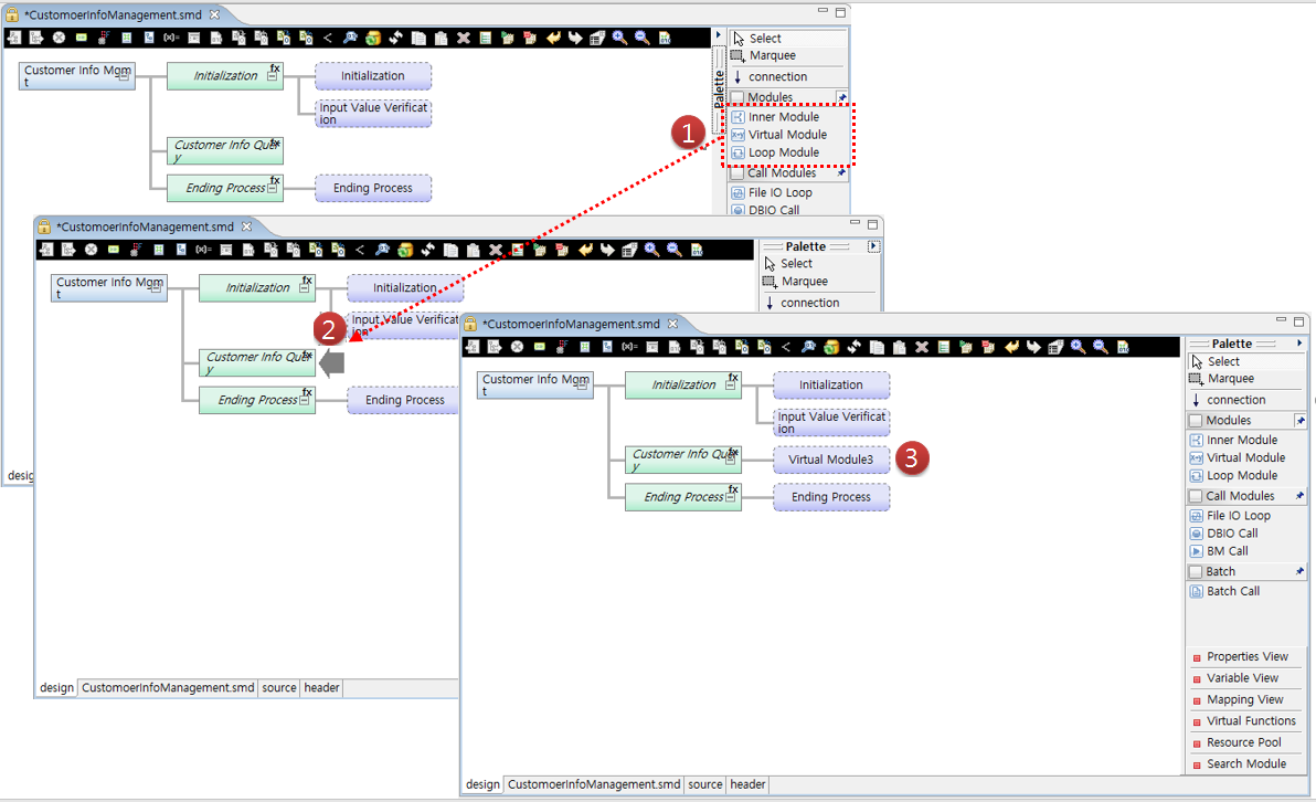
Virtual Module |
Expressed as the {…} paragraph in source. Inserted between modules, and the source code needs to be manually written. Virtual modules cannot have a submodule. |
Loop Module |
Expressed as a While statement in source. Used to repeatedly process subnodes of a submodule. |
The general modules can be placed in Design Editor with the following steps.
The following describes Inner, Virtual, and Loop modules in detail.
Inner Module
In EMB Designer, external modules such as business and DBIO modules can be called and also virtual modules created as internal functions can be used to control an application flow. A representative virtual module is an Inner module.
Inserting an Inner module shows the static function calling part at the location of the node in actual source and creates the function implementation part under the source. The function cannot be called externally and can only be used internally. A conditional statement can be inserted before the function calling part, and an exception handling statement can be inserted after the part. In addition, local variables can be declared and used in the function implementation part.
The following are the steps for creating an Inner module.
-
In EMB Designer, click Inner Module from Palette and drag and drop it to a desired location in Module Editor.
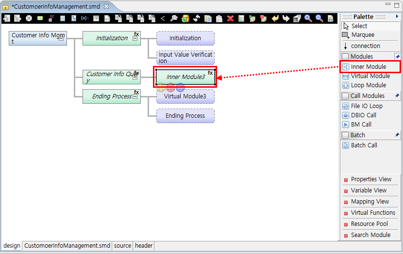 Example of Inner Module Creation
As shown in the previous figure, circular buttons are shown below the Inner module. Clicking one of them goes to a corresponding source code area. Hovering over one of them shows a tooltip that says the button type. For more information about the circular buttons, refer to EMB Buttons.
-
To check source of the created Inner module, click the source tab at the bottom. In the source, there is a function that calls the Inner module created in an EMB module function.
① static long InnerModule2(CustomerInfoManagermentContext \*context)
{
    long rc = RC_NRM;
    // User Variables Declaration
    {
        /**************************************
         * KIND     : Intermediary Module Function Call
         * NODE ID  : 9
         * NAME     : InnerModule3
         * DESCRIPTION :
         *
         *************************************/
②      PFM_TRY(InnerModule3(context));
        //DO_NOT_MODIFY_THIS_LINE-----------START_OF_CODE:INNER_MODULE_EXCEPTION NODEID9------------------//

        //DO_NOT_MODIFY_THIS_LINE-----------END_OF_CODE:INNER_MODULE_EXCEPTION NODEID9------------------//
    }
    return RC_NRM;
PFM_CATCH:
    return rc;
}
The following describes the previous source.
① Created EMB module function (CustomerInfoManagement).
② Calls the InnerModule3 function.
In Source Editor, you can only edit the part enclosed with "//DO_NOT_MODIFY_THIS_LINE…" and the part under "DESCRIPTION :" which means module comment.
In the source, there is the InnerModule3 function implementation part under the created EMB module function (CustomerInfoManagement). A subnode inserted to the InnerModule3 module is inserted to the function implementation part as follows:
/************************************** * KIND : Intermediary Module Function * NODE ID : 9 * NAME : InnerModule3 * DESCRIPTION : * *************************************/ static long InnerModule3(CustomerInfoManagermentContext *context) { long rc = RC_NRM; // User Variables Declaration return RC_NRM; PFM_CATCH: return rc; } -
Click Properties View from Palette.
-
Set properties of the created Inner module in the properties view.
The following describes each property of an Inner module.
Category and Property Description Condition
Comments
Inserts comments to an If conditional statement.
Condition
Inserts an If conditional statement to the entry point of the code area to control the flow.
Exception
Exception
Whether to execute exception handling.
Exception Code
Inserts exception handling code.
Exception Throw
Whether to handle an exception occurred during execution.
Ignore Exception Flag
Whether to ignore exception handling.
Information
Comment
Inserts module comments.
Function Name
Renames a function created in source.
Kind
Whether the created Inner module source is Function or Block.
Name
Sets a logical module name.
Reference Module
Sets an Inner module that is actually referenced.
Variable
Declare Code
Manually declares a variable in source.
Variable
Opens a dialog box where local variables can be declared.
Others
Disabled
Whether to disable a module. Source is not created for disabled module.
Group id
Currently not used.
Level
Currently not used.
Node id
Component ID that is unique in EMB
Parent node id
Parent component ID that is unique in EMB.
Position
Currently not used.
The following describes how to set the 'Kind' and 'Reference' module properties.
-
Kind
 Inner Module – Kind Property Setting
If you change the 'Kind' property from 'function' to 'block', the node of the Inner module is changed. That is, fx at the top right of the Inner module node is removed.
The following is an example.
Before Change After Change 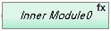
Changing the 'Kind' property modifies the source as follows:
static long InnerModule2(CustomerInfoManagermentContext \*context)
{
    long rc = RC_NRM;
    // User Variables Declaration
①  {
        /**************************************
         * KIND     : Intermediary Module Block
         * NODE ID  : 9
         * NAME     : InnerModule3
         * DESCRIPTION :
         *
         *************************************/
        // User Variables Declaration
②  }

    return RC_NRM;
PFM_CATCH:
    return rc;
}
In the previous source, changing the 'Kind' property to 'block' shows 'Brace({…})' in the part from ① to ②. To avoid unnecessary function creation and improve source readability, set the property to 'block'.
-
Reference Module
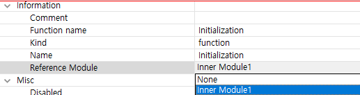 Inner Module – Reference Module Property Setting
Clicking the 'Reference Module' property shows the list of Inner modules in the current flow diagram. Select one of them and save it. The color of the selected Inner module’s node is changed to gray.
The following is an example.
Before Change After Change 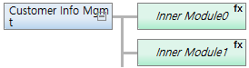
Changing the 'Reference Module' property modifies the source as follows:
{
        /**************************************
         * KIND     : Intermediary Module Function Call
         * NODE ID  : 2
         * NAME     : InnerModule1
         * DESCRIPTION :
         *
         *************************************/
①      PFM_TRY(InnerModule1(context));
        //DO_NOT_MODIFY_THIS_LINE-----------START_OF_CODE:INNER_MODULE_EXCEPTION NODEID2------------------//

        //DO_NOT_MODIFY_THIS_LINE-----------END_OF_CODE:INNER_MODULE_EXCEPTION NODEID2------------------//
    }
    {
        /**************************************
         * KIND     : Intermediary Module Function Call
         * NODE ID  : 7
         * NAME     : InnerModule1
         * DESCRIPTION :
         *
         *************************************/
②       PFM_TRY(InnerModule1(context));
        //DO_NOT_MODIFY_THIS_LINE-----------START_OF_CODE:INNER_MODULE_EXCEPTION NODEID7------------------//

        //DO_NOT_MODIFY_THIS_LINE-----------END_OF_CODE:INNER_MODULE_EXCEPTION NODEID7------------------//
    }
In the previous source, ① and ② do not implement or call a function. They call the selected Inner module.
If a specific logic is repeatedly necessary in a flow diagram, make is as a business module for code efficiency and reusability. However, if the logic is too small or has inappropriate content to be a module, it is recommended to change the 'Reference Module' property.
-
Virtual Module
Virtual modules are expressed as the Brace ({…}) paragraph where developers can write code. These modules can be inserted between various modules whenever they are necessary to make connections in source code.
The following are the steps for creating a Virtual module.
-
In EMB Designer, click Virtual Module from Palette and drag and drop it to a desired location in Module Editor.
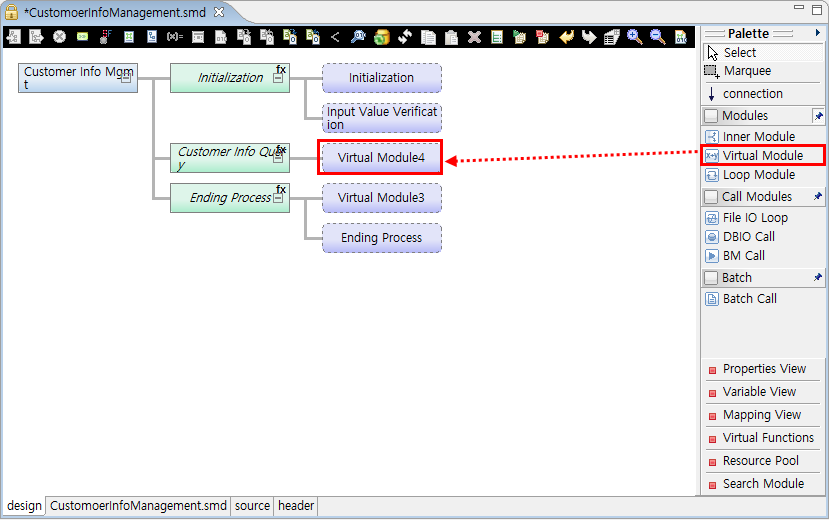 Example of Virtual Module Creation
Circular buttons are shown below the Virtual module. Clicking one of them goes to a corresponding source code area. Hovering over one of them shows a tooltip that says the button type. For more information about the circular buttons, refer to EMB Buttons.
-
To check source of the created Virtual module, click the source tab at the bottom. In the source, the created Virtual module area exists in an Inner module function.
static long innerModule2(CustomerInfoManagermentContext *context)
{
    long rc = RC_NRM;

    // User Variables Declaration
    {
        /**************************************
         * KIND     : Virtual Module
         * NODE ID  : 7
         * NAME     : VirtualModule4
         * DESCRIPTION :
         *************************************/
①      //DO_NOT_MODIFY_THIS_LINE-----------START_OF_CODE:VIRTUAL_MODULE NODEID7------------------//
        // TODO Auto-generated method stub
②      //DO_NOT_MODIFY_THIS_LINE-----------END_OF_CODE:VIRTUAL_MODULE NODEID7------------------//

    }
    return RC_NRM;
PFM_CATCH:
    return rc;
}
The part from ① to ② is the created Virtual module area.
In Source Editor, you can manually write code in the "// TODO.." area and use properties view functions.
-
Click Properties View from Palette.
-
Set properties of the created Virtual module in the properties view.
The following describes each property of an Inner module.
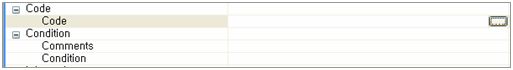
Category and Property Description Code
Code
Write code to insert to source.
Condition
Comments
Inserts comments to an If conditional statement.
Condition
Inserts an If conditional statement tp the entry point of the code area to control the flow.
Information
Comment
Inserts module comments.
Name
Sets a logical module name.
Others
Disabled
Whether to disable a module. Source is not created for disabled module.
Group id
Currently not used.
Level
Currently not used.
Node id
Component ID that is unique in EMB
Parent node id
Parent component ID that is unique in EMB.
Position
Currently not used.
Since Virtual modules are blocks to insert only code to Source Editor unlike Inner modules, they have not many properties.
The following describes how to set the 'Code' module property.
 Virtual Module – Code Property Setting
Click […] to open the Edit Code dialog box where you can write code.
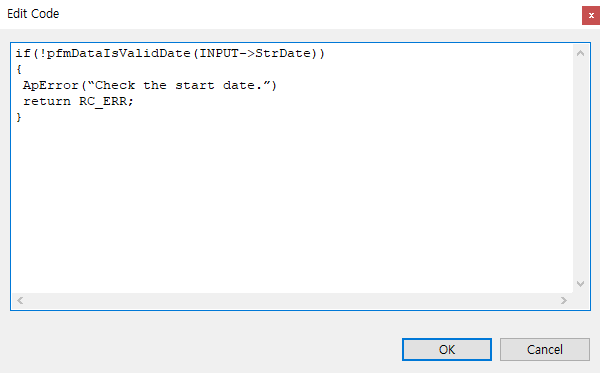 Virtual Module – Sample Edit Code
Write code in the dialog box and then click [OK]. This has the following two results.
First, the 'Code' property value is changed in the properties view.
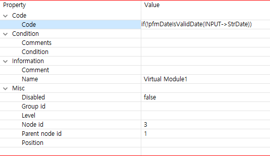 Virtual Module – Changed Code Property Value
Second, the source code is modified as follows:
static long innerModule2(CustomerInfoManagermentContext *context)
{
    long rc = RC_NRM;

    // User Variables Declaration
    {
        /**************************************
         * KIND     : Virtual Module
         * NODE ID  : 7
         * NAME     : VirtualModule4
         * DESCRIPTION :
         *************************************/
        //DO_NOT_MODIFY_THIS_LINE-----------START_OF_CODE:VIRTUAL_MODULE NODEID7------------------//
      ① if (!pfmDateIsValidDate(INPUT->StrtDate))
         {
            ApError("Check the start date.");
            return RC_ERR;
      ②}
        //DO_NOT_MODIFY_THIS_LINE-----------END_OF_CODE:VIRTUAL_MODULE NODEID7------------------//
    }
    return RC_NRM;

PFM_CATCH:
    return rc;
}
The code written in the Edit Code dialog box is inserted in the part from ① to ②.
Loop Module
Loop modules are expressed as a While statement in source and used to repeatedly process child nodes of a created Loop module.
The following are the steps for creating a Loop module
-
In EMB Designer, click Loop Module from Palette and drag and drop it to a desired location in Module Editor.
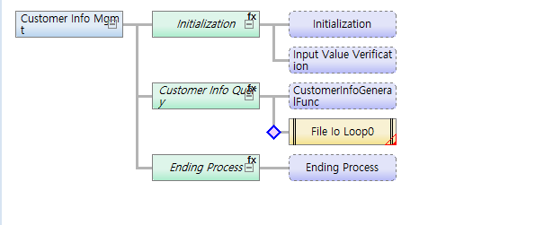
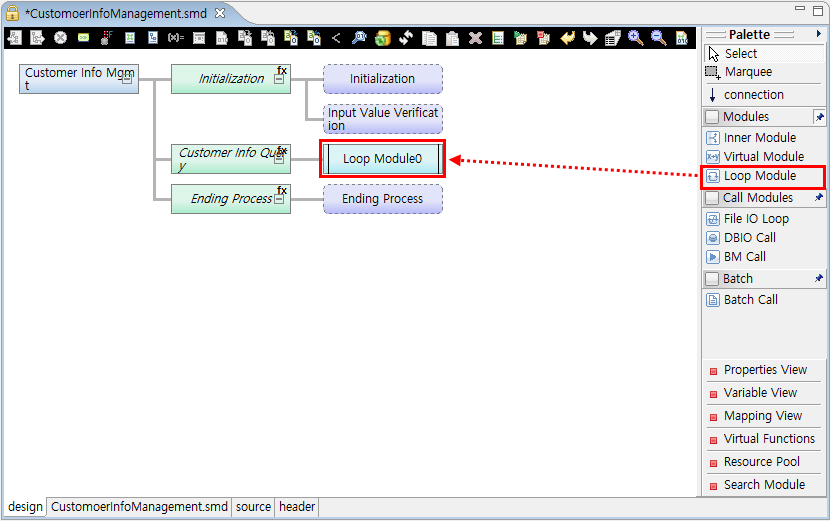 Example of Loop Module Creation
Circular buttons are shown below the Loop module. Clicking one of them goes to a corresponding source code area. Hovering over one of them shows a tooltip that says the button type. For more information about the circular buttons, refer to EMB Buttons.
-
To write pre and post-processing code of the created Loop module, select and right-click the Loop module. Click the Loop Pre/Post processing menu.
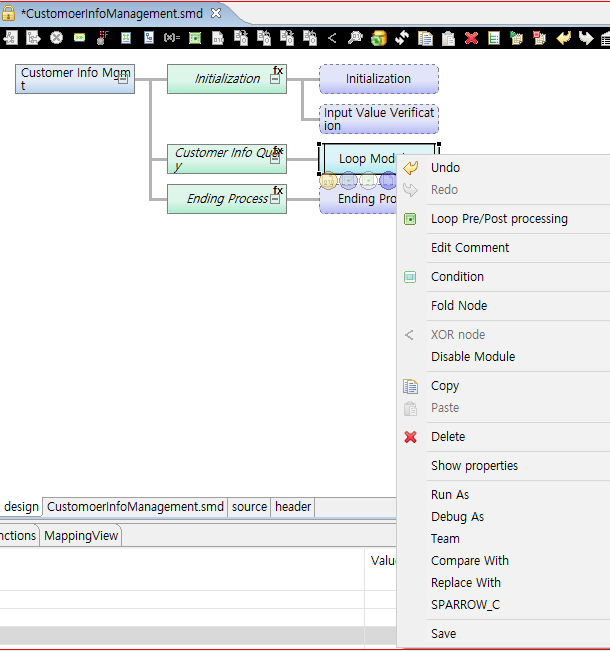 Loop Module – Menu for Loop Module
 -
The Loop Pre/Post processing dialog box where you can write pre and post-processing code is displayed. In this example, write 'while(test) {' in Loop PreProcessing and '}' in Loop PostProcessing, where test is an iteration condition.
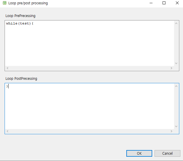 Loop Module – Loop Pre/Post processing
 -
To check source of the created Loop module, click the source tab at the bottom. In the source, the created Loop module code exists in an associated Inner module function.
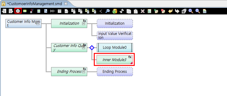
static long innerModule2(CustomerInfoManagermentContext *context)
{
    long rc = RC_NRM;

    // User Variables Declaration
    {
        /**************************************
         * KIND     : Loop Module
         * NODE ID  : 8
         * NAME     : LoopModule0
         * DESCRIPTION :
         *
         *************************************/
        //DO_NOT_MODIFY_THIS_LINE-----------START_OF_CODE:LOOP_MODULE_PRE NODEID8------------------//
       ① while(test){
        //DO_NOT_MODIFY_THIS_LINE-----------END_OF_CODE:LOOP_MODULE_PRE NODEID8------------------//

        //DO_NOT_MODIFY_THIS_LINE-----------START_OF_CODE:LOOP_MODULE_POST NODEID8------------------//
       ② }
        //DO_NOT_MODIFY_THIS_LINE-----------END_OF_CODE:LOOP_MODULE_POST NODEID8------------------//
    }
    return RC_NRM;

PFM_CATCH:
    return rc;
}
The following describes the previous source.
① You can check the code (while(test) {) written in Loop PreProcessing of the Loop Pre/Post processing dialog box.
② You can check the code (}) written in Loop PostProcessing of the Loop Pre/Post processing dialog box.
If a subnode is added to the Loop module, source code is inserted to the while statement in the previous source.
-
Click Properties View from Palette.
-
Set properties of the created Loop module in the properties view.
The following describes each property of an Inner module.
Category and Property Description Pre/Post Processing
Pre Processing
Write a pre-processing condition for a loop statement.
Post Processing
Write a post-processing condition for a loop statement. Typical source code is '}'.
The code written in the Loop Pre/Post processing dialog box is shown in the properties view.
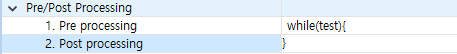 Loop Module – Pre/Post Processing Property Setting
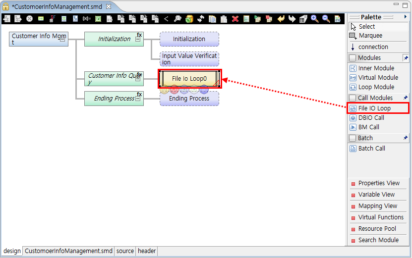
3.2.2. Call Modules
In Palette, there are the following Call modules: File IO Loop, DBIO Call, and BM Call modules. For more information, refer to Call Modules.
The Call modules can be placed in Design Editor as follows:
The following describes each Call modules.
-
File IO Loop
A Loop module for FileIO. This module is similar to a loop module, but the exact number of repetitions can be specified and exception handling is possible.
-
DBIO Call
A DBIO module is searched from a resource pool and inserted. However, only resources of operating area (RI) can be searched.
-
BM Call
A Business module is searched from a resource pool and inserted. However, only resources of operating area (RI) can be searched.
3.2.3. Batch Modules
In Palette, there is the following Batch modules: Batch Call module. For more information about call modules, refer to Call Modules.
3.3. Call Modules
In this guide, modules that are externally created and not the modules provided in EMB Designer are called as Call modules. The Call modules are used to call a function that cannot be automatically created in EMB Designer.
Call modules can be used when creating a flow of an EMB module. For example, they can call interface functions of Business, DBIO, and Batch modules.
Each Call module has the 'Module Target' property in the properties view. By changing this property value, the target module to call can be selectively replaced by a resource in RI or WS area for unit tests. A resource that selects a RI area calls a RI resource when calling a unit test, and the module name is displayed in the screen. A resource that selects a WS area calls a WS resource when calling a unit test, and the module name preceded by 'WS-' is displayed in the screen.
| Module | Description |
|---|---|
Service Module |
Used for a created module to call a Service module. |
Business Module |
Used for a created module to call a Business module. |
Batch Module |
Used for a created module to call a Batch module. |
Persist DBIO Module |
Used for a created module to call a DBIO module of the Persist query type. |
DynamicSQL DBIO Module |
Used for a created module to call a DBIO module of the DynamicSQL query type. |
View DBIO Module |
Used for a created module to call a DBIO module of the View query type. |
Fetch DBIO Module |
Used for a created module to call a DBIO module of the Fetch Exec type. |
ExecSQL DBIO Module |
Used for a created module to call a DBIO module of the ExecSQL query type. |
|
The previous each module cannot have a submodule. |
The following describes each module’s properties.
-
Common properties for Call modules
Category and Property Description Condition
Comments
Comments about entry conditions.
Condition
Conditions to enter the module.
Exception
Exception Code
Exception code to handle an exception occurred when processing a called module right after calling the module without executing PFM_CATCH code.
Ignore Exception
Whether to execute PFM_CATCH code for an exception occurred when processing a called module or ignore the exception to process the next flow.
Module Target
Module Target
Whether to refer to called module information from the operating area or workspace area.
Others
Disabled
Whether to disable a module. Source is not created for disabled module.
Group id
Currently not used.
Level
Currently not used.
Node id
Component ID that is unique in EMB
Parent node id
Parent component ID that is unique in EMB.
Position
Currently not used.
-
Service Module
Category and Property Description Call Property
Callee name
Associated Service module name.
Call kind
Service call type.
-
L: dlcall
-
R: tpcall
Shared post-processing
Whether to execute system post-processing.
Shared pre-processing
Whether to execute system pre-processing.
Sync
Service module’s sync mode.
-
dlcall: Always uses a sync method.
-
tpcall: Can call a service with an async method.
Team Shared post-processing
Whether to execute an application post-processing module.
Team Shared pre-processing
Whether to execute an application pre-processing module.
Transaction
Whether to handle a called service with one transaction or a separate transaction.
Debug
Print Debug
Outputs input/output structure values of DBIO for debugging.
I/O
Input structure name
Input structure name of a Call module.
Output structure name
Output structure name of a Call module.
Information
Called function
Function name to call.
Library path
Library path.
Logical name
Logical name.
Physical name
Physical name.
Resource id
Resource ID.
Resource Path
Resource path.
Tx code
Service module’s Tx code.
Transformation
In type transform
Input structure mapping method.
Out type transform
Output structure mapping method.
-
-
Business Module
Category and Property Description Debug
Print Debug
Outputs input/output structure values of DBIO for debugging.
Exception
Exception Code
Exception code to handle an exception occurred when processing a called module right after calling the module without executing PFM_CATCH code.
Exception Type
Name of a function to call when an exception occurs.
Ignore Exception
Whether to execute PFM_CATCH code for an exception occurred when processing a called module or ignore the exception to process the next flow.
I/O
Input structure name
Input structure name of a Call module.
Output structure name
Output structure name of a Call module.
Information
Library path
Library path.
Logical name
Logical name.
Physical name
Physical name.
Resource id
Resource ID.
Resource Path
Resource path.
Return type
Return type.
Transformation
In type transform
Input structure mapping method.
Out type transform
Output structure mapping method.
-
DBIO Module
Category and Property Description DBIO call parameter
Array Kind
Array structure type.
-
Array of Structure
-
Structure of Array
Count
Actual array size to use.
Dynamic Parameter
Manually write code that sets parameters when using dynamic SQL.
Lock Mode
Whether to use a lock when searching for SELECT and FETCH Exec types.
DBIO In/Out call
Execution Type
INSERT, UPDATE, DELETE, SELECT, or FETCH Exec type.
Lock Query
Whether to execute a lock query.
Max Count
Maximum available array size.
Wait time
Wait time to use when using a lock query.
Debug
Print Debug
Outputs input/output structure values of DBIO for debugging.
I/O
Array input structure name
Array input structure name.
Array output structure name
Array output structure name
Dynamic structure name
Dynamic variable structure name for DynamicSQL queries.
Input structure name
Input structure name.
Output structure name
Output structure name
Information
Logical name
Logical name.
Physical name
Physical name.
Resource id
Resource ID.
Resource Path
Resource path.
Transformation
In type transform
Input structure mapping method.
Out type transform
Output structure mapping method.
-
-
Batch Module
Category and Property Description Information
Comments
Comments for Batch modules.
Name
Logical name of a Batch module.
Information(Batch)
Args
Arguments used when calling a Batch module.
Calling Call Modules
There are the following three methods to call a Call module.
-
Call a Call module from Navigator area.
-
Call a Call module from a resource pool view. Only resources in ProFrame Navigator (RI) area can be searched.
-
Call a Call module in Palette.
Category Submenu Call Modules
-
DBIO Call
-
BM Call
Batch
-
Batch Call
-
Mapping Call Modules
A Call module is designed in the form of a black box, so that it can be reused by multiple modules. In order for another module to call a Call module, it needs to process input parameters and input/output conversion for result values.
Select a called Call module and right-click it to select [Transformation] > [Input transformation]. This opens the following Map Dialog.
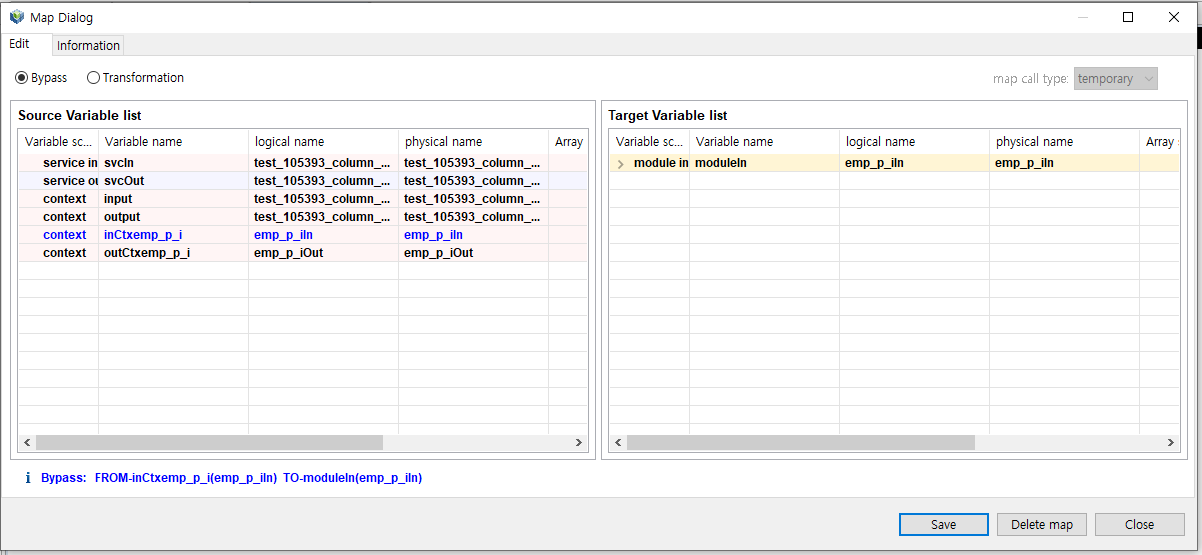
After defining mapping for input parameters, click [Save]. Defining mapping for output parameters is the same as in input conversion. The pink background means that the structure is in an operating image area, and the light green background means that the structure is in a working area.
|
For more information about input/output conversion, refer to ProFrame ProMapper Developer Guide. |
3.4. Virtual Functions
Virtual functions can be inserted to a flow diagram of an EMB module.
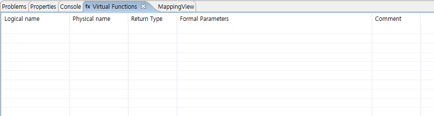
Click Virtual Functions in Palette. Right-click the Module Editor area of EMB Designer to select the Show the list of Virtual Functions menu.
The following are the steps for creating a function by using the Virtual Functions view.
-
Right-click the Virtual Functions view and select the [Create a Virtual Function] menu. This opens the Configure Virtual Function dialog box.
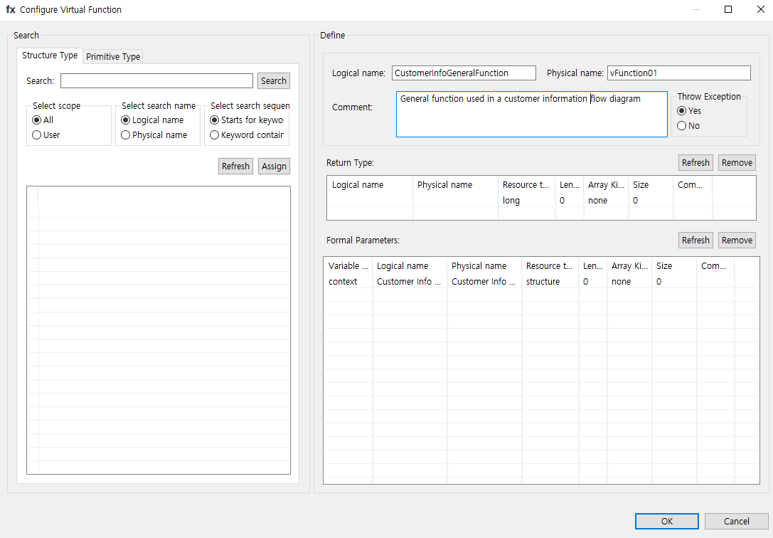 Configure Virtual Function
-
Logical name, Physical name
Logical and physical names of a function to create.
-
Comment
Comment for a function to create.
-
Throw Exception
Option for a function to create to handle an exception. If set to 'Yes', the return type must be long.
-
Return Type
Sets the return type of a function to create.
Item Description Logical name
Logical name of the return type.
Physical name
Physical name of the return type.
Resource type
Resource type of the return type. (For example, string, long)
Length
Return type length.
Array Kind
Array type of the return type.
-
none
-
fixed
-
variable
Size
Array size of the return type.
Comment
Comment for the return type.
-
-
Formal Parameters
Defines parameters of a function to create.
Item Description Variable name
Variable name of a function to create.
Logical name
Logical name of a function to create.
Physical name
Physical name of a function to create.
Resource type
Resource type of a function to create.
Length
Length of a function to create.
Array Kind
Array type of a function to create.
Size
Array size of a function to create.
Comment
Comment for a function to create.
To define parameters, use the Search area in Configure Virtual Function.
Tab Description Structure Type
Searches for input parameters of registered structures.
Primitive Type
Sets input parameters of the basic units such as letters and numbers.
-
-
Set all items required to create a function in Configure Virtual Function and click [OK]. A created function can be checked from the Virtual Functions view.
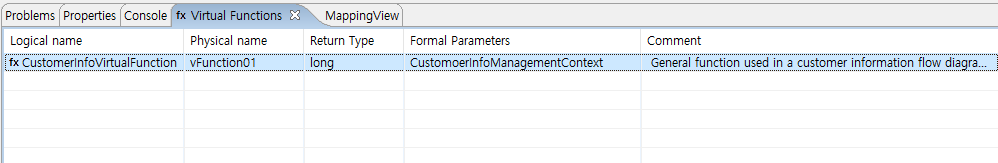 Virtual Functions – Function Creation Result
 -
To create a logic that will be executed in a general function, Right-click the created function to select the Edit Code menu.
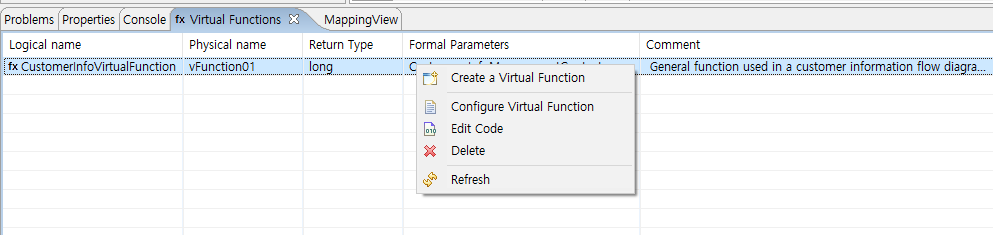 Virtual Functions – Edit Code
 -
Write code in the open Edit Code dialog box. In this example, the following code is written.
FMW_DBG("***********************") FMW_DVG("**Virtual Function Test**") FMW_DBG("***********************") -
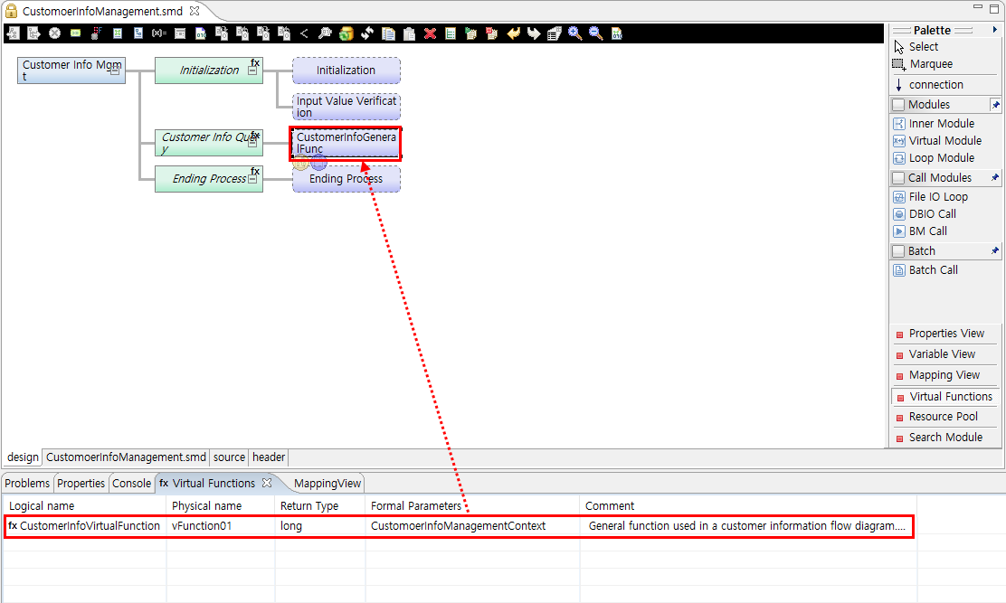
To place the created virtual function in a flow diagram of an EMB module, select the function in the Virtual Functions view and drag and drop it in a desired position.
 Inserting Function
To check the source code in Source Editor, double-click the inserted function node.
/**************************************
 * KIND     : Virtual Function
 * NODE ID  : 1
 * NAME     : vFunction01
 * DESCRIPTION :
 * General function used in a customer info flow diagram.
 *************************************/
① static long vFunction01(CustomerInfoManagermentContext *context)
{
//DO_NOT_MODIFY_THIS_LINE-----------START_OF_CODE:VIRTUAL_FUNCTION NODEID1------------------//
② FMW_DBG("***********************")
③ FMW_DVG("**Virtual Function Test**")
④ FMW_DBG("***********************")
}
//DO_NOT_MODIFY_THIS_LINE-----------END_OF_CODE:VIRTUAL_FUNCTION NODEID1------------------//
The following describes the previous source.
① Created function (vFunction01).
② - ④ Source code written in the Edit Code dialog box.
4. Editing a Flow
To implement an EMB module in more detail, add Business or other logic to a service or application flow diagram that is designed in EMB Designer.
The following describes how to add logic to a flow diagram of an EMB module and edit a flow of the module.
4.1. Entry Conditions
An entry condition controls the flow of a module to be executed according to a specific condition. By using an if statement, it allows to execute the flow only when the specific condition is met.
The following are the steps for setting an entry condition.
-
Select and right-click a module for which an entry condition is set. Select [Condition] from the context menu.
-
The following Condition dialog box opens. Enter a specific condition or add a combination of variables and operators.
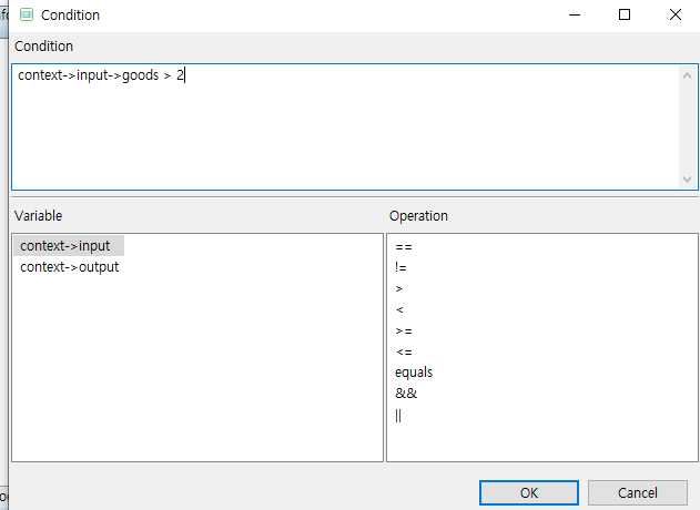 Condition Dialog Box
Item Description Condition
Edition area where a specific condition is entered.
Variable
List of variables that are available for an entry condition.
Operation
Operators that are available for an entry condition.
Enter a condition and then click [OK] to complete the entry condition setting.
The following is the source code (for the condition entered in Condition Dialog Box) that you can check in Source Editor.
static long innerModule2(CustomerInfoManagermentContext *context)
{
    long rc = RC_NRM;
    // User Variables Declaration
①  if(
    //DO_NOT_MODIFY_THIS_LINE-----------START_OF_CODE:LOOP_MODULE_CONDITION NODEID8------------------//
        context->input->goods > 2
    //DO_NOT_MODIFY_THIS_LINE-----------END_OF_CODE:LOOP_MODULE_CONDITION NODEID8------------------//
②  )

        /**************************************
         * KIND     : Loop Module
         * NODE ID  : 8
         * NAME     : LoopModule0
         * DESCRIPTION :
         *
         *************************************/
        //DO_NOT_MODIFY_THIS_LINE-----------START_OF_CODE:LOOP_MODULE_PRE NODEID8------------------//
③     while(test){
        //DO_NOT_MODIFY_THIS_LINE-----------END_OF_CODE:LOOP_MODULE_PRE NODEID8------------------//

        //DO_NOT_MODIFY_THIS_LINE-----------START_OF_CODE:LOOP_MODULE_POST NODEID8------------------//
        }
        //DO_NOT_MODIFY_THIS_LINE-----------END_OF_CODE:LOOP_MODULE_POST NODEID8------------------//
    }
    return RC_NRM;

PFM_CATCH:
    return rc;
}
The following describes the previous source.
①, ② Source code for the condition entered in Condition Dialog Box.
③ Source code of the loop module where the entry condition is set.
-
Check the entry condition in Module Editor.
 Entry Condition Setting
4.2. XOR Node/Reset
XOR processing is to set an entry condition (if statement) for a selected module and then select and process multiple modules to be processed with an else if statement.
XOR Node
The following are the steps for setting the XOR node function.
-
Select and right-click a module to set an XOR node. Select [<(XOR node)] from the context menu.
-
Modules selected for an XOR node are combined as a node as follows. The XOR node icon in toolbox of EMB Designer is enabled.
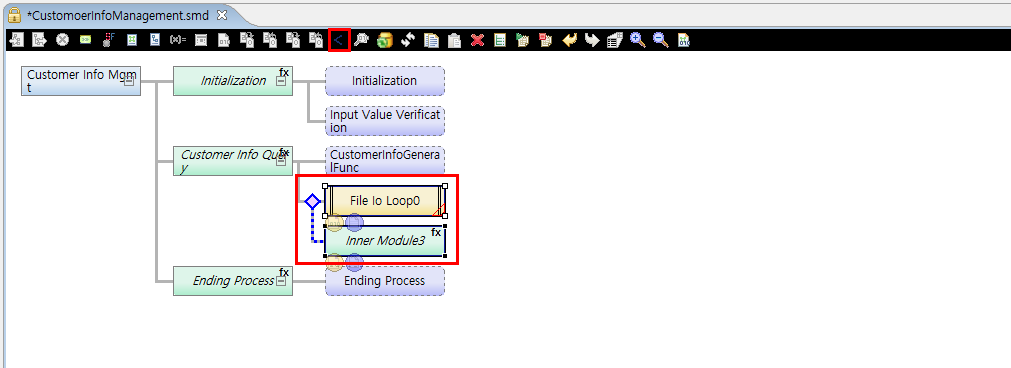 XOR Node Result
 -
To check the source code with the else if statement, double-click the module.
XOR Reset
The following are the steps for setting the XOR reset function.
-
Select and right-click a module for which an XOR node was set. Select [<(Reset XOR)] from the context menu.
-
Modules that were combined as a node are divided. The set else if statement is removed from the source code.
 XOR Reset Result
4.3. Exception Handling and Its Code Edition
Exception handling is to handle errors that can occur in a selected module and the module’s subnodes.
Exception Handling
The following are the steps for setting exception handling.
-
Select and right-click a module. Select [Exception] from the context menu.
If exception handling is set for an Inner module, the last module among submodules is responsible for handling errors. Therefore, typically place a Virtual module in the last position to make it handle errors.
-
A red triangle mark is displayed in the lower right corner of the last node of a module for which exception handling is set. The exception handling icon in toolbox of EMB Designer is enabled.
 Exception Handling Setting Result
 -
Check the source code for the last subnode in Source Editor.
...
    return RC_NRM;

①  PFM_CATCH:
    {
        /**************************************
②       * KIND     : Intermediary Module Function Call
         * NODE ID  : 9
         * NAME     : InnerModule3
         * DESCRIPTION :
         *
         *************************************/
        PFM_TRYNJ(InnerModule9(context));
        //DO_NOT_MODIFY_THIS_LINE-----------START_OF_CODE:INNER_MODULE_EXCEPTION NODEID9------------------//

        //DO_NOT_MODIFY_THIS_LINE-----------END_OF_CODE:INNER_MODULE_EXCEPTION NODEID9------------------//
    }
③  return rc;
}
The following describes the previous source.
① - ③ Source code for exception handling.
② The last node of the module (Virtual module in this example) for which exception handling is set.
Call and Inner modules can call internal and external functions in source code. You can check the code enclosed in PFM_TRY. If an error occurs while calling this ProFrame function, it goes to PFM_CATCH that handles errors.
Therefore, the last node (Virtual module) plays the role in this example. If you want to sequentially execute a flow without going to PFM_CATCH even when an error occurs, use [Edit Exception Code].
Editing Code for Exception Handling
The following are the steps for editing exception handling code.
-
Select and right-click a module for which exception handling is set. Select [Edit Exception Code] from the context menu.
-
Check the source code for PFM_TRY of the module in Source Editor.
{
        /**************************************
         * KIND     : Intermediary Module Function Call
         * NODE ID  : 2
         * NAME     : Customer Info Query
         * DESCRIPTION :
         *
         *************************************/
①      PFM_TRY(innerModule2(context));
        //DO_NOT_MODIFY_THIS_LINE-----------START_OF_CODE:INNER_MODULE_EXCEPTION NODEID2------------------//
②
        //DO_NOT_MODIFY_THIS_LINE-----------END_OF_CODE:INNER_MODULE_EXCEPTION NODEID2------------------//

}
The following describes the previous source.
① PFM_TRY function of the module.
② Writing source code in this part automatically modifies PFM_TRY to PFM_TRYNJ. PFM_TRYNJ makes a flow to be sequentially executed even if the called module returns an error. Deleting all the source code in this part automatically modifies PFM_TRYNJ to PFM_TRY again.
4.4. Definition
In EMB Designer, you can define various variables that are available in source code.
The following is how to define variables.
-
Click an appropriate definition button in toolbox of EMB Designer.
-
Use the [Definition] context menu in Module Editor of EMB Designer.
Define various variables by selecting [Definition] in Module Editor of EMB Designer.
| Variable Definition | Description |
|---|---|
CommBuff definition |
Selects CommBuff structure that is used to send data between service modules. Available for service, pre-processing, and post-processing modules. |
Constant definition |
Defines constants that are used in a module. |
Context definition |
Defines structures and variables of context that is used in a module. Context is a structure that has all input/output structures that are used for a context flow as members by default. It is used as a parameter when calling an internal function. |
Structure definition |
Defines structures that are used in a module. |
CommBuff Definition
CommBuff is a variable loaded to shared memory. Using CommBuff can improve system performance because cached variables are used.
Select [Define commbuff] menu to open the following Define commbuff dialog box.
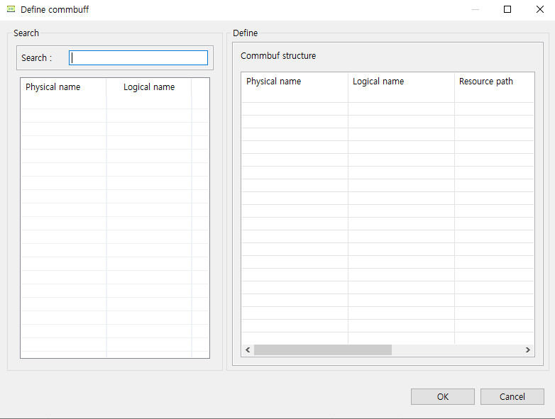
In the Search section, CommBuffs defined in WebAdmin are displayed. Therefore, to see CommBuffs in EMB Designer, system administrators must register them in advance.
|
If the Define commbuff dialog box is opened when no CommBuff is registered in WebAdmin, the message that says "Failed to load commbuff list." is displayed. That is, CommBuff cannot be defined. |
In the Define section, CommBuffs used by a current EMB module are displayed. To use CommBuff that is defined in a current EMB module in a service or pre or post-processing module, search for the CommBuff from the Search section and then drag and drop it to the Define section.
Constant Definition
Select [Define constant] menu to open the following Define constant dialog box.
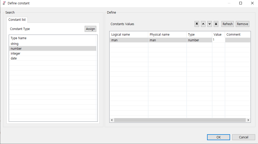
You can set types, values, and comments in this dialog box. The set constants are included in a header file.
Select and double-click a constant type to create a constant of the type in the Define section. Define the constant by editing a logical name, physical name, value, and comment.
In this example, the 'CONSTANT_TEST' constant of the string type is defined as "TEST". Check the creation result in Header File Viewer.
// Constants
#define CONSTANT_TEST "TEST" /* constant definition */
Context Definition
Context is a structure that has all input/output structures that are used for a context flow. It is used as a parameter when calling an internal function. Developers can add new structures and basic variables if necessary.
Select [Define context] menu to open the following Define context dialog box.
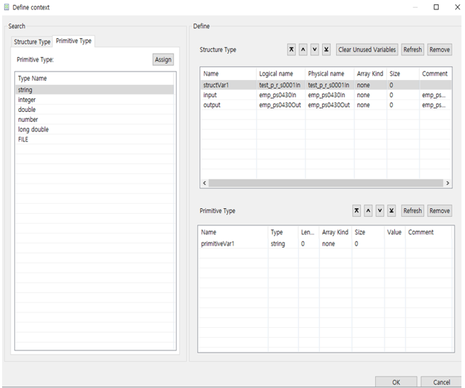
To add an existing structure in the Define section, use the [Structure Type] or [Primitive Type] tab in the Search section.
In this example, the structVar1 structure and the primitiveVar1 context variable of the string type are declared. Check the declaration result in Header File Viewer.
/ Context Data
typedef struct {
    test_clob_qpstest_p_sIn structVar1;

    /*test_dept_qpstest_p_s2In(test_dept_qpstest_p_s2In) */
    test_dept_qpstest_p_s2In *input;

    /*test_dept_qpstest_p_s2Out(test_dept_qpstest_p_s2Out) */
    test_dept_qpstest_p_s2Out *output;
    char primitiveVar1[0 + 1];
} CustomerInfoManagementContext;
Structure Definition
Select [Define structure] menu to open the following Define structure dialog box.
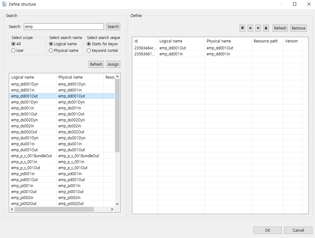
To add an existing structure in the Define section, search the structure from the Search section.
In this example, structures that start with 'em' are searched for: emp_qpstest_p_sIn and emp_qpstest_p_sOut. The searched results are declared as structure variables. Check the declaration result in Header File Viewer.
// Includes Structs
#include <pfmMapperemp_qpstest_p_sIn.h> // emp_qpstest_p_sIn
#include <pfmMapperemp_qpstest_p_sOut.h> // emp_qpstest_p_sOut
4.5. Module Info Reconfiguration
If there are any changes in an existing module to be called, the module’s information is reconfigured in a flow that will call the module. If this function is not used, a compilation error or unexpected result can occur. Therefore, if there are any module changes, use the [Reconfigure Module Info] menu to reconfigure the module’s information.
This function is usually used for a module’s input/output structure changes. It is also needed for DBIO modules' parameter changes.
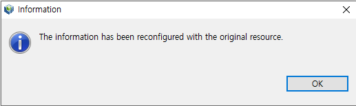
For example, an existing structure of a module to be called can be changed. If the structure source is used by another area, this opens a dialog box that asks whether you want to delete the source. If there is no reconfiguration issue, the following Information window is displayed.
4.6. Comments Edition
Addition descriptions about each node can be added and edited. For example, select an Inner module and then select the [Edit Comment] menu. This opens the following Edit Comment dialog box.
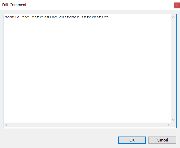
The comments written in the dialog box can be checked in source code.
{
        /**************************************
         * KIND     : Intermediary Module Function Call
         * NODE ID  : 2
         * NAME     : InnerModule1
         * DESCRIPTION :
①       * Module for retrieving customer information
         *************************************/
}
The following describes the previous source.
① The comments written in the Edit Comment dialog box.
4.7. Module Movement
To change the flow order or position of an EMB module, click the connecting line between nodes. At this time, select the black point between nodes and drag and drop it to a desired position.
A node itself can also be moved by dragging and dropping it. At this time, the positions of all subnodes of the selected node are changed depending on the position of gray arrow displayed and the order of the source code is also changed.
5. Compilation and Dlupdate
After creating and editing the flow of an EMB module, compile the module and execute Dlupdate. If the resource that will use RI/WS is an RI resource, compile RI resources and execute Dlupdate. If the resource is a WS resource, compile WS resources and execute Dlupdate.
Compilation
The following are methods for compiling an EMB module.
-
Select and right-click a created EMB module from Navigator. From the context menu, select the [Compile Resource] menu.
-
Use the shortcut key: <Alt> + C.
-
Use the compilation icon embedded in Studio.
The EMB module source loaded in a server’s file system is compiled with a compiler embedded in the server. The progress and result can be checked in Console of Studio.
Dlupdate
The following are methods for executing Dlupdate.
-
Select and right-click a created EMB module from Navigator. From the context menu, select the [Dlupdate] menu.
-
Use the shortcut key: <Alt> + D.
-
Use the Dlupdate icon embedded in Studio.
The compiled EMB module source is combined as a single library and then loaded in shared memory. This process allows for processes to use the same version of library and also hot deploy that needs integrity.
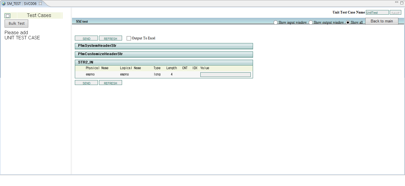
6. Unit Test
Perform a unit test to check whether a created EMB module operates normally.
|
Unit tests can be performed only for Service and Business modules. For more information about unit tests, refer to ProFrame Unit Test Guide. |
Select a created EMB module to test and right-click Navigator. From the context menu, select the [Unit Test] menu. Enter values to each field of the input structure and then click [SEND]. This displays the test result.