Starting ProMapper
This chapter describes how to create ProMapper and relevant details and functions.
1. Overview
This chapter describes the following for ProMapper module creation.
-
Adding basic information for each resource type
Select menu for each resource type and add basic information related to creation in ProMapper dialog box. For detailed information, refer to Adding Basic Information for Each Resource Type.
-
Using an editor for each resource type
How to use editors for each resource type: Structure, Message, and Map. For detailed information, refer to Using an Editor for Each Resource Type.
-
Source generation, compilation, and Dlupdate
How to generate source, compile, and execute Dlupdate for each type of ProMapper resources. For detailed information, refer to Source Generation, Compilation, and Dlupdate.
2. Adding Basic Information for Each Resource Type
The following describes how to add basic information for each resource type.
2.1. Structure
The following are the steps for adding basic information about a structure.
-
Select [New] > [Structure] from the context menu of Workspace Navigator.
-
The following New Structure Wizard opens. In this dialog box, basic information required to create a structure can be added.
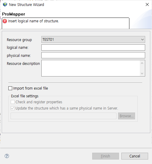 New Structure Wizard
The following describes each item.
Item Description Resource group
Resource group. (Required)
Only resource groups that are registered in WebAdmin are displayed. If a desired resource group does not exist, add the resource group in WebAdmin. To add a resource group, log in to WebAdmin and select [META SYSTEM] from the main screen and then select [META SYSTEM] > [ResourceGroupMgmt]. In the ResourceGroupMgmt screen, check currently set resource groups and then register the resource group to add.
logical name
Logical name of a structure to add.
physical name
Physical name of a structure to add.
Resource description
Description about a structure to add.
Import from excel file
Imports an Excel template file that includes structure information.
If this check box is selected, the Resource group, logical name, physical name, and Resource description items are disabled.
The following example imports an Excel template file.
-
Excel file creation
Enter structure information to an Excel file in the following format. Set the fields and values in appropriate positions (columns and rows).
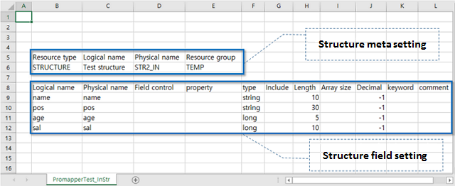 Excel Template File
 -
Structure creation
Select [New] > [Structure] from the context menu of Workspace Navigator.
-
Import setting
Select the 'Import from excel file' check box in New Structure Wizard.
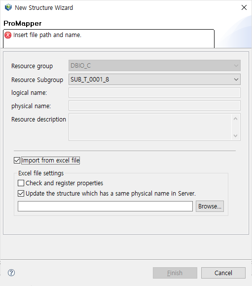 New Structure Wizard – Import from Excel File
The following describes each item that is enabled when selecting the 'Import from excel file' check box.
Item Description Check and register properties
Check whether meta data exists in a server. If not, field data in an Excel template file is registered in meta and then the structure information is retrieved.
Update the structure which has a same physical name is SErver.
If a server has a structure that is the same as that retrieved from an Excel template file, the Excel file reads the server structure and changes existing data to the server structure data.
Search for the created Excel file by clicking [Browse..].
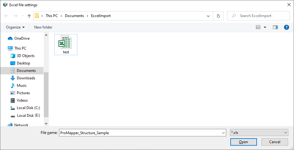 Import from Excel File – File Search
 -
Structure field comparison
Check whether the column data retrieved from the Excel file match meta fields from the Compare to the information of fields of this structure window.
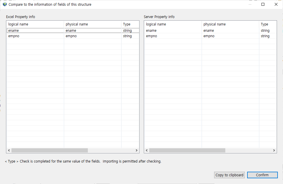 Import from Excel File – Structure Field Comparison (Match)
If there is a field that does not match, the field is highlighted.
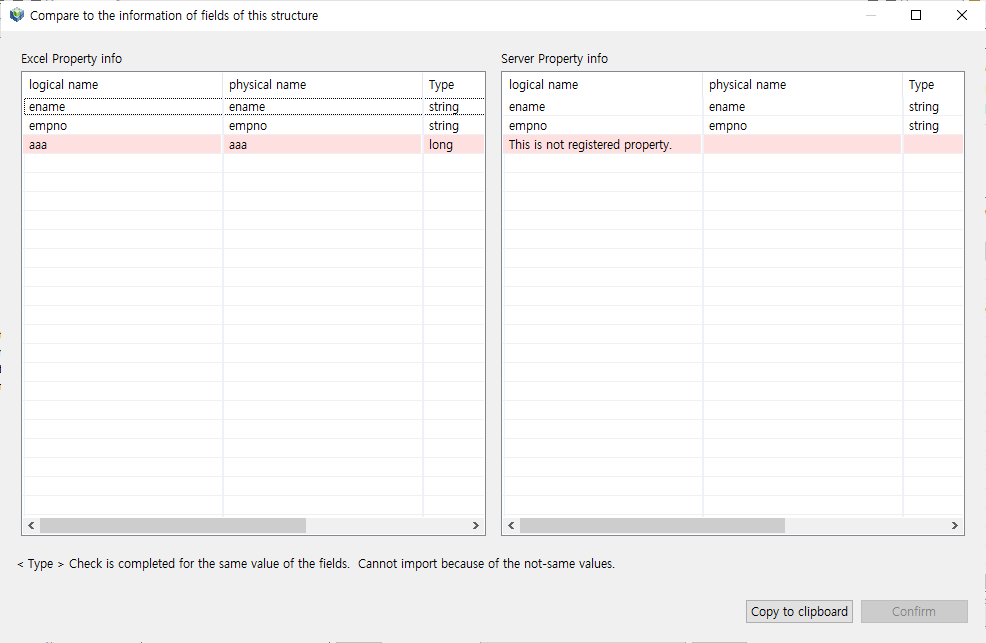 Import from Excel File – Structure Field Comparison (Not Match)
 -
Structure edition
Structure data defined in the Excel template file is displayed in Structure editor.
The following shows that column values of the file are added in the editor.
 Import from Excel File – Structure Edition
-
-
After setting all basic information in New Structure Wizard, click [Finish] to go to the screen where you can edit structures. For information about Structure editor, refer to Structure Editor.
2.2. Message
The following are the steps for adding basic information about a message.
-
Select [New] > [Message] from the context menu of Workspace Navigator.
The following New Message Wizard opens. In this dialog box, basic information required to create a message can be added.
 New Message Wizard
The following describes each item.
Item Description Resource group
Resource group. (Required)
Only resource groups that are registered in WebAdmin are displayed. If a desired resource group does not exist, add the resource group in WebAdmin. To add a resource group, log in to WebAdmin and select [META SYSTEM] from the main screen and then select [META SYSTEM] > [ResourceGroupMgmt]. In the ResourceGroupMgmt screen, check currently set resource groups and then register the resource group to add.
Message Type
Message type.
-
FixedLength: Fixed-length type. Fields are identified based on the fixed length.
-
Delimiter: Variable-length type. Fields are identified with a delimiter.
logical name
Logical name of a message to add.
-
MsgFld: 'MsgFld' is automatically appended after the developer-defined logical name. This word can be modified with MESSAGE_LOGICAL_SUFFIX and MESSAGE_LOGICAL_SUFFIX_FLD in WebAdmin.
-
MsgDel: 'MsgDel' is automatically appended after the logical name if Message Type is set to Delimiter. This word can be modified with MESSAGE_LOGICAL_SUFFIX and MESSAGE_LOGICAL_SUFFIX_DEL in WebAdmin.
physical name
Physical name of a message to add.
-
MsgFld: 'MsgFld' is automatically appended after the developer-defined physical name. This word can be modified with MESSAGE_PHYSICAL_SUFFIX and MESSAGE_PHYSICAL_SUFFIX_FLD in WebAdmin.
-
MsgDel: 'MsgDel' is automatically appended after the physical name if Message Type is set to Delimiter. This word can be modified with MESSAGE_PHYSICAL_SUFFIX and MESSAGE_PHYSICAL_SUFFIX_DEL in WebAdmin.
-
-
After setting all basic information in New Message Wizard, click [Finish] to go to the screen where you can edit messages. For information about Message editor, refer to Message Editor.
2.3. Map
The following are the steps for adding basic information about a map.
-
Select [New] > [Mapping] from the context menu of Workspace Navigator.
The following New Mapping Wizard opens. In this dialog box, basic information required to create a message can be added.
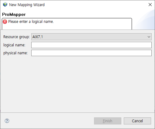 New Mapping Wizard
The following describes each item.
Item Description Resource group
Resource group. (Required)
Only resource groups that are registered in WebAdmin are displayed. If a desired resource group does not exist, add the resource group in WebAdmin. To add a resource group, log in to WebAdmin and select [META SYSTEM] from the main screen and then select [META SYSTEM] > [ResourceGroupMgmt]. In the ResourceGroupMgmt screen, check currently set resource groups and then register the resource group to add.
logical name
Logical name of a map to add.
physical name
Physical name of a map to add.
-
After setting all basic information in New Map Wizard, click [Finish] to go to the screen where you can edit maps. For information about Map editor, refer to Map Editor.
3. Using an Editor for Each Resource Type
The following describes how to use editors for each resource type: Structure, Message, and Map.
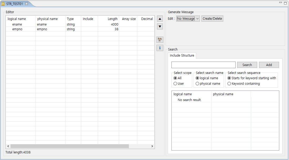
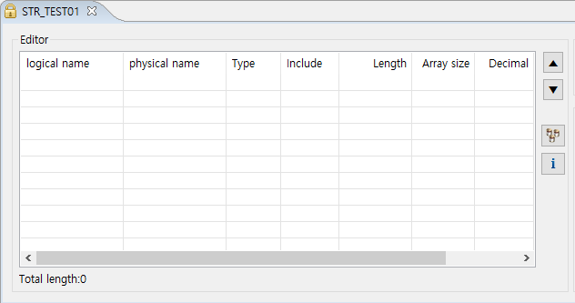
3.1. Structure Editor
Structure editor consists of the following three areas.
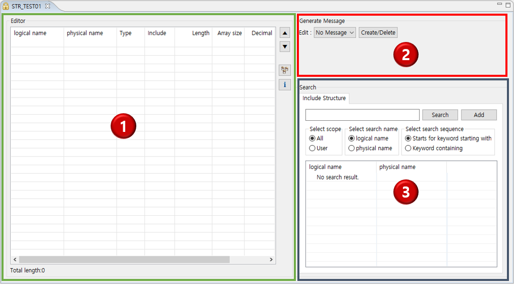
① Editing area
② Message creation area
③ Structure search area
Editing area
Adds and edits structure fields, and creates a structure with a set of other structures.
The following describes each item and icon.
| Item & Icon | Description |
|---|---|
logical name |
Logical name of a structure field. |
physical name |
Physical name of a structure field. |
Type |
Type of a structure field. |
Include |
Another structure to include when the field type is "include". |
Length |
Length of a structure field. |
Array size |
Number of repetitions of a structure field. |
Decimal |
Number of digits after the decimal point. |
Description |
Description about a structure field. |
▲ |
Moves a structure field up. |
▼ |
Moves a structure field down. |
|
Opens the Synchronize Dialog dialog box where you can synchronize server’s meta data and structure field data. |
|
Opens a dialog box where you can check basic information about registered structures |

To synchronize server’s meta data and structure field data, click the  icon. This opens the Synchronize Dialog dialog box that has Structure and Property (meta) sections. In the Structure section, current structure’s field data is displayed. In the Property section, server’s meta data is displayed. If there is no meta data that matches the current structure, the message of "Meta not found." is displayed in the Property section.
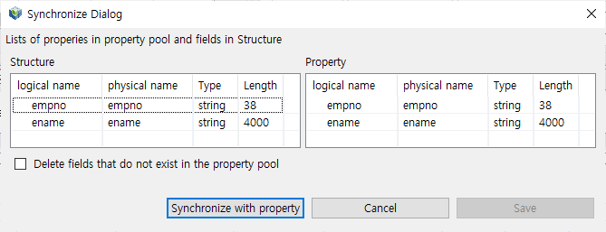
Clicking [Synchronize with property] changes structure field data to server’s meta data. When the synchronization is complete, [Save] is enabled. To apply the changed structure filed data, click [Save].
|
For unregistered meta data, select [META SYSTEM] > [META SYSTEM] > [MetaMgmt] > [Property Mgmt] in WebAdmin and add it in the open Property Mgmt page. |
Message creation area
Creates a message that has 1:1 relationship with a structure.
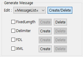
The following describes each item.
| Item | Description |
|---|---|
Edit |
Opens a dialog box where you can edit a message when selecting a created message. |
FixedLength |
To create a FixedLength message, click [Create]. To delete a FixedLength message, click [Delete]. |
Delimiter |
To create a Delimiter message, click [Create]. To delete a Delimiter message, click [Delete]. |
FDL |
Unsupported message type. |
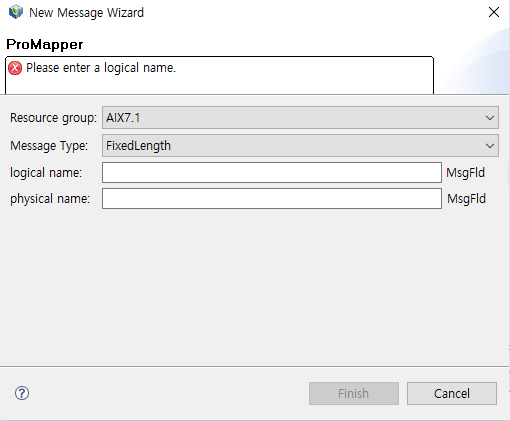
Clicking [Create] next to FixedLength or Delimiter automatically creates a message that has 1:1 relationship with a structure. If a message is created, the message type is listed in the Edit drop-down list. Since the message has 1:1 relationship with a structure, it is not required to create a map.
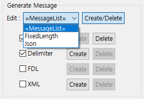
To edit an automatically created message, select the message’s type from the Edit drop-down list. This opens a dialob box where you can edit the message.
|
Usage of the dialog box for message edition is the same as that for structures. |
The following describes how to edit created messages of each type.
-
FixedLength
Consists of [Edit] and [Information] tabs. In the [Edit] tab, you can edit messages depending on the selected message type. In the [Information] tab, you can check basic structure information (basic ProMapper module information).
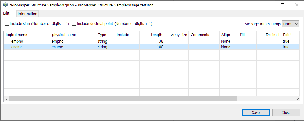 Structure Editor – Dialog Box for Message Edition – FixedLength
The following describes each item for FixedLength messages of the number type.
Item Description Include sign (Number of digits + 1)
Adds 1 (the sign length) to the length of each field after defining all filed lengths.
Include decimal point (Number of digits + 1)
Adds 1 (the decimal point length) to the length of each field after defining all filed lengths.
Message trim settings
How to trim messages.
-
rtrim: Removes spaces at right. (Default value)
-
ltrim: Removes spaces at left.
-
lrtrim: Removes spaces at left or right.
-
None: Does not remove spaces.
The following describes each column.
Column Description logical name
Logical name of a structure field.
physical name
Physical name of a structure field.
Type
Type of a structure field.
(Example: long, number, string)
Include
Physical message name if the already registered message is used as a structure field.
Length
Length of a structure field.
Array size
Number of repetitions of a structure field.
Comments
Additional description about a structure field.
Align
Alignment of a structure field.
Fill
Character to append to FixedLength message whose length is less than the specified length.
Decimal
Expression of decimal places.
Point
Option to display a decimal point.
Sign
Option to display a sign.
Delimiter
Delimiter when the message type is Delimiter.
EncodeOption
Message encoding option.
-
-
Delimiter
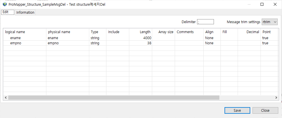 Structure Editor – Dialog Box for Message Edition – Delimiter
The following describes the Delimiter item.
Delimiter Description. ;
(Default value)
Others
You can use any character as a delimiter.
Structure search area
Searches existing structures and adds fields to a structure in Structure editor.
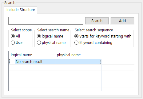
The following describes each item.
-
Buttons
Button Description [Search]
Searches for operating area (ReleaseImage, RI) structures based on an entered structure name and search condition.
[Add]
Adds a selected structure to Structure editor.
-
Search conditions
Condition Description Select scope
All, User
Select search name
logical name, physical name
Select search sequence
Starts for keyword starting with, Keyword containing
-
Search result
Item Description logical name
Logical name of a structure.
physical name
Physical name of a structure.
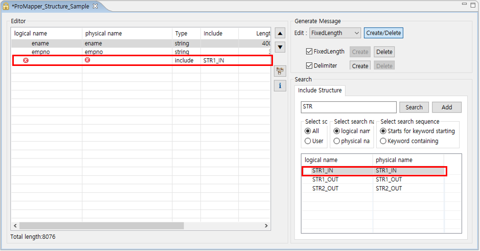
3.1.1. Adding Structures
The following describes how to add a searched structure to Structure editor.
To add a searched structure to Structure editor, use one of the following methods.
-
Clicking [Add]
Select a structure to add and click [Add].
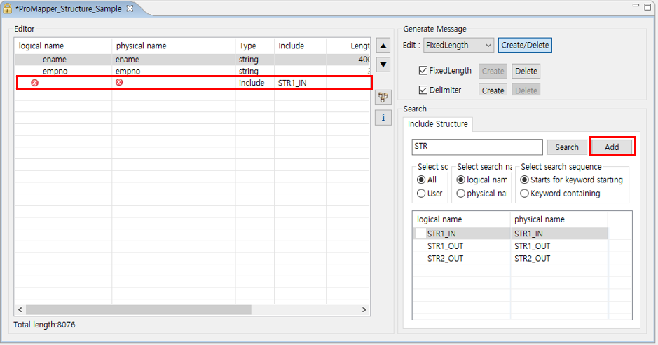 Structure Editor – Structure Search Area – [Add] Button
 -
Double-clicking
Select and double-click a structure to add.
 Structure Editor – Structure Search Area – Double-clicking
 -
Drag-and-drop
Drag and drop a structure to add.
 Structure Editor – Structure Search Area – Drag-and-drop
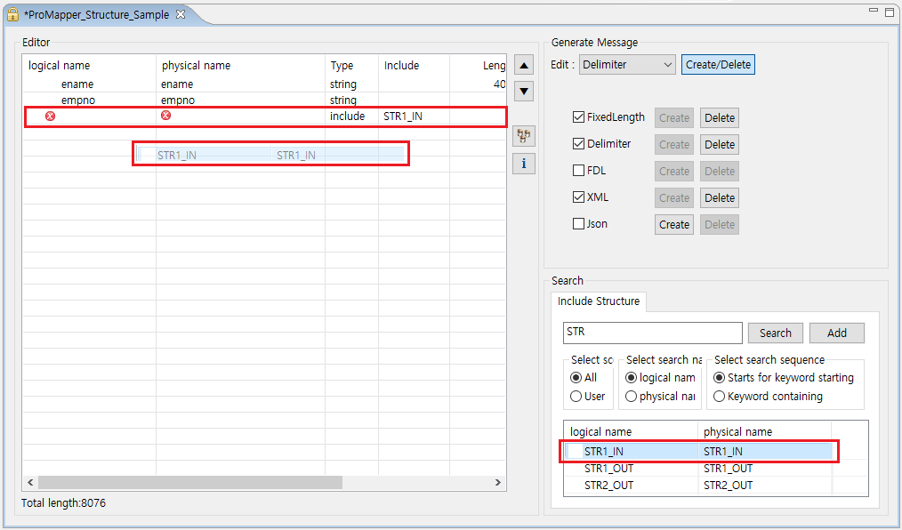
The following shows the result of adding a structure.
Added structures can be reused by changing logical and physical names.
The following describes each icon that can be shown in the result table.
| Icon | Description |
|---|---|
|
Means unregistered meta or missing required structure field value. Hovering over it shows a tooltip for troubleshooting. |
|
Means that server’s meta data does not match. Most mismatch reasons are a data type, length, and logical name. Check mismatch reasons and change filed or meta data. |

3.1.2. Editing Structures
The following describes useful functions and how to add fields to Structure editor.
There are two methods of editing structures: using the editing function or an Excel file.
The following describes how to edit Structures.
-
Editing function
Use the editing function available only in editing area of Structure editor.
 Structure Editor
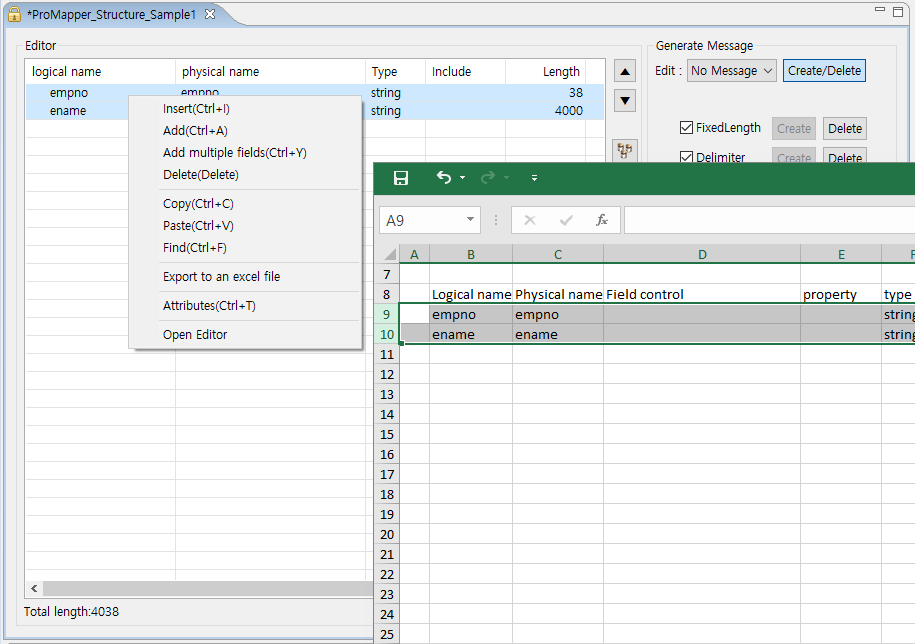
The following is the context menu of the editing area.
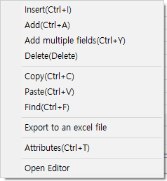 Structure Editor – Editing Function Menu
The following describes each menu.
Menu Description Insert(Ctrl+I)
Inserts a new field before a selected structure field.
Add(Ctrl+A)
Adds a new field after the structure field that is currently shown in editing area of Structure editor.
Add multiple fields(Ctrl+Y)
Adds multiple structure fields at once.
Delete(Delete)
Deletes selected fields.
Copy(Ctrl+C)
Copies selected fields.
Paste(Ctrl+V)
Pastes copied fields.
Find(Ctrl+F)
Finds a column location with logical or physical name.
Export to an excel file
Exports structure field data to an Excel file.
Attributes(Ctrl+T)
Shows structure field attributes.
Open Editor
Opens Structure editor if a selected field is a structure.
The following describes the [Export to an excel file] menu.
To export a created structure to an Excel file, click [Export to an excel file]. This opens the Export to an excel file dialog box. Specify the file location and click [Save].
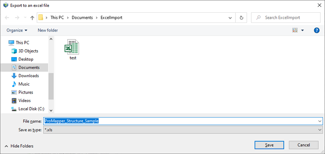 Editing Function – Export to an Excel File
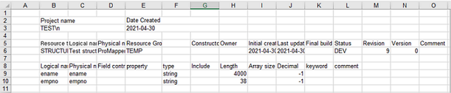 Editing Function – Result Excel File
The following describes each item in the result Excel file.
Item Description Project name
Project name.
Date Created
Date when a structure is exported to the Excel file.
The following describes each structure data in the result Excel file.
Item Description Resource type
Structure.
Logical name
Logical name of a structure.
Physical name
Physical name of a structure.
Resource Group
Resource group of a structure.
Constructor
Structure constructor.
Owner
Structure owner.
Initial creation time
Structure creation time.
Last update time
Structure update time.
Final build time
Structure build completion time.
Status
Structure status. (For example, development, error, compile completion)
Revision
Structure revision. One is added whenever a structure is updated.
Version
Configuration version.
Comment
Additional description about a structure.
New structure fields can be added. When adding a field as described, the field can be edited.
To edit a structure field, select and double-click the field to display it in editing area. For example, a text editor opens for text, a combo box editor opens for types with many properties. Use the open editor to enter the field value. You can edit multiple structure fields by copying and pasting them. Also, you can copy fields from an Excel file and search for specific fields.
-
Using an Excel file
Write information required to create a structure in an Excel file, and then copy the information and paste it to Structure editor.
 Using an Excel File – Copy & Paste
Unlike the import function, meta data is not automatically created for Items copied from an Excel file. Therefore, when pasting the Excel data to Structure editor, the
 icon is displayed if meta data is not registered. To resolve this issue, click button to synchronize server’s meta data.
For unregistered meta data, select [META SYSTEM] > [META SYSTEM] > [MetaMgmt] > [Property Mgmt] in WebAdmin and add it in the open Property Mgmt page.
3.1.3. Adding Fields in Structure Editor
The following describes how to add general and structure fields in Structure editor.
-
General fields
Add general fields in Structure editor by typically using the Property Pool view. If the view is not displayed, select [Window] > [Open Perspective] > [Other…] > [ProFrame Studio] > [Property Pool] in Studio.
Add general structure fields by searching meta data registered in WebAdmin from the Property Pool view. For information about how to register and manage meta in WebAdmin, refer to ProFrame Administrator Guide.
The following shows the Property Pool view.
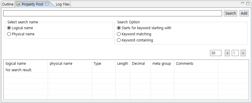 Property Pool
Enter meta name to search or set search conditions (name and option) and then click [Search].
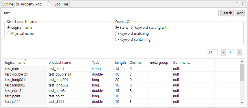 Property Pool Search Result
Meta data that satisfies the search conditions is displayed. If there is no search result, the message saying "No search result." is displayed. To add the searched meta data in Structure editor as a general field, select the meta data and then double-click or drag and drop it.
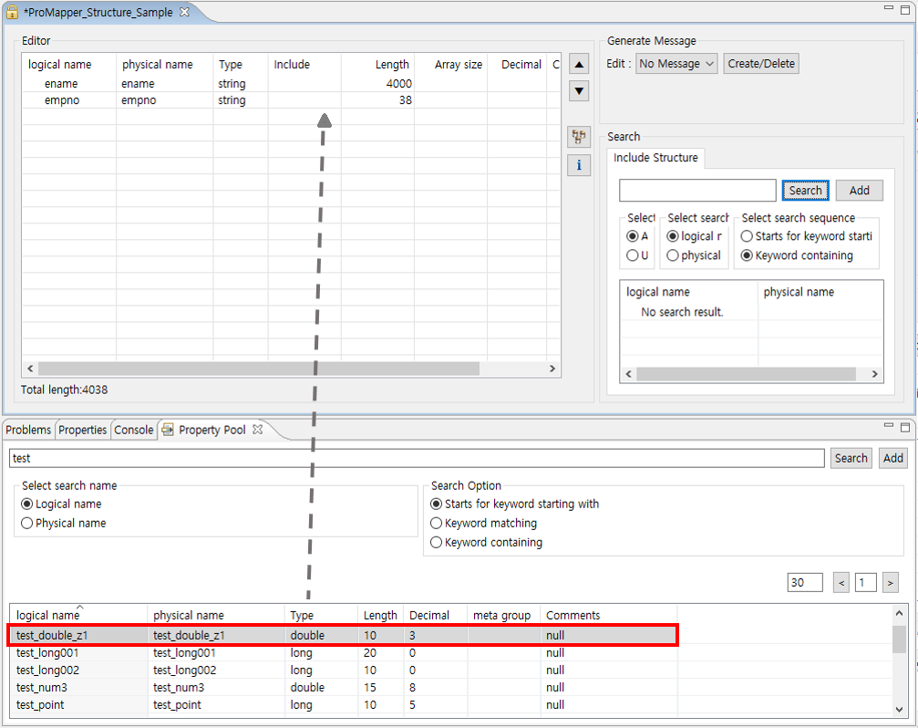 Property Pool Search Result – Adding Data to Structure Editor
In the previous figure, you can check that a selected meta data is added to Structure editor.
-
Structure fields
Add structure fields in Structure editor by searching structures. The following is how to edit the added structure fields.
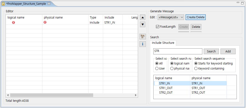 Structure Editor – Editing Structure Fields
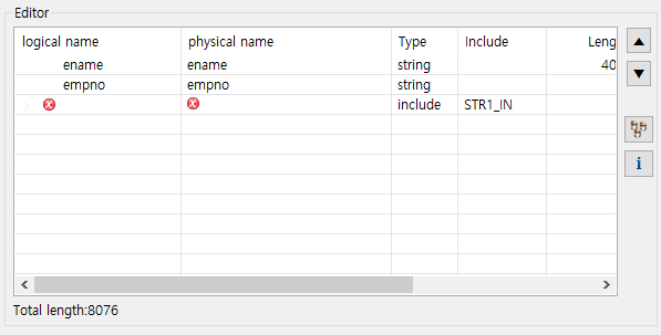
Before editing a structure field, check the field added in the Editor area by clicking [+] in the logical name column.
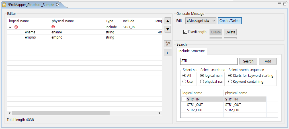 Structure Editor – Structure Field Information
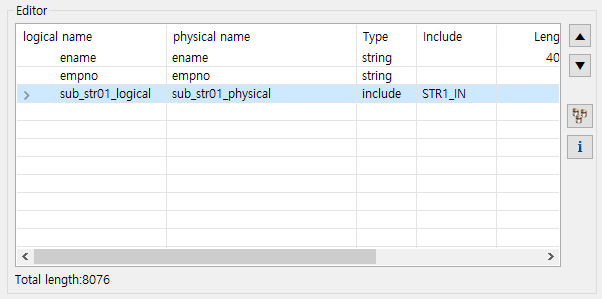
After checking the structure field information, enter the added structure’s logical and physical names. In this example, the logical name is 'str1_in_logical' and the physical name is 'str1_in_physical'.
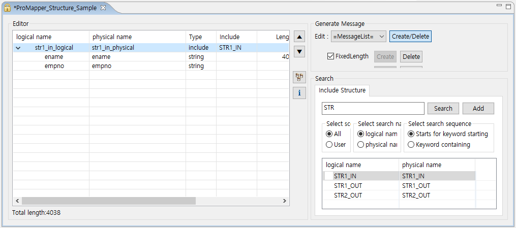 Structure Editor – Entering Logical and Physical Names
Select [Open Editor] from the context menu.
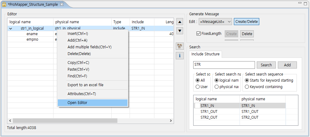 Structure Editor – Open Editor
Clicking [Open Editor] goes to a page where you can edit added structure fields. If RI/WS is used, you cannot edit them and can only view them.
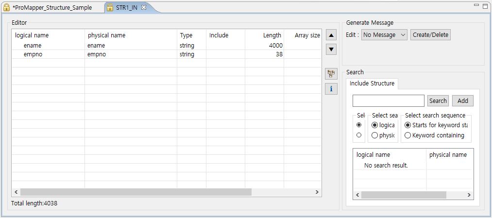 Structure Editor – Structure Field Edition Page
The following describes each column.
Column Description logical name
Logical name of a structure field.
physical name
Physical name of a structure field.
Type
Structure field type.
Include
Structure’s physical name is padded to a value for structure fields.
Length
Length of a structure field.
Array size
Number of repetitions of a structure field.
Decimal
Number of digits after the decimal point of a structure field.
Description
Description about a structure field.
3.2. Message Editor
Message editor consists of the following two areas.
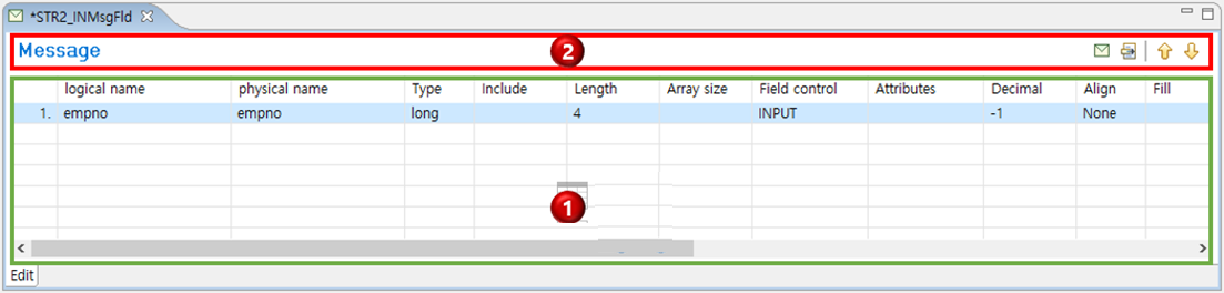
① Editing area
② Icon bar
Editing area
Adds and edits messages. Note that structure messages can be edited by using an editing combo box in Structure editor.
| Column | Description |
|---|---|
logical name |
Logical name of a field. |
physical name |
Physical name of a field. |
Type |
Field type. |
Include |
Another structure to include when the field type is "include". |
Length |
Length of a field. |
Array size |
Number of repetitions of a field. |
Field control |
Field’s component type. (Example: INPUT, OUTPUT, GRID, COMBO, CHECKBOX, LISTVIEW, LABEL, BUTTON, GROUPBOX, OCCURS, RADIOBUTTON, PWDINPUT, CHART, IMAGE) |
Decimal |
Number of digits after the decimal point. |
Align |
Field alignment. |
Fill |
Character to append to a specific value. |
Point |
Option to display a decimal point. |
Sign |
Option to display a sign. |
Trim |
How to handle spaces. |
Delimiter |
Delimiter when the message type is Delimiter. |
EncodeOption |
Message encoding option. |
Field key |
Field key used when the message type is FDL. |
Comments |
Additional description about a field. |
Required |
Whether the field is required. |
Icon Bar
Shows useful icons that can be used for message edition.
| Icon | Description |
|---|---|
|
Opens the Resource Pool view where you can search for operating area (ReleaseImage, RI) messages. |
|
Opens the Property Pool view where you can search for general structure fields. |
|
Moves a selected field up. Enabled only for messages created through New Message Wizard. |
|
Moves a selected field down. Enabled only for messages created through New Message Wizard. |


The following describes about the  icon that opens the Resource Pool view under the Message Editor.
In the Resource Pool view, you can search for ProFrame’s all resources by using various search conditions.
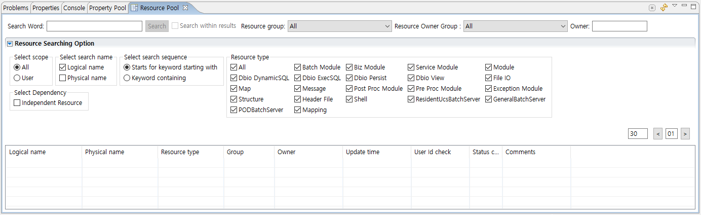
|
For information about how to use the Resource Pool view, refer to ProFrame Studio Guide. |
3.3. Map Editor
Map editor consists of the following three areas. In this Map editor, you can set mapping rules for created structures and messages.
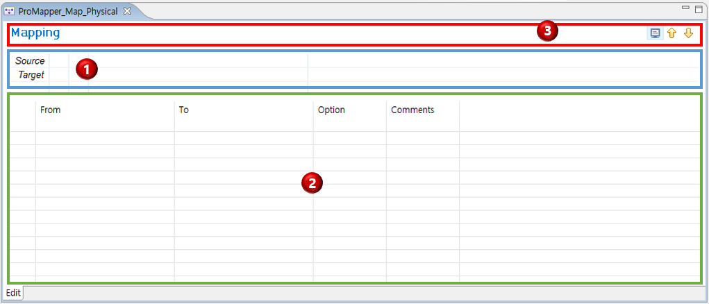
① Source and target specification area
② Editing area
③ Icon bar
Source and target specification area
Specifies a source and target. Search for an operating area (ReleaseImage, RI) structure or message that is required for mapping and then drag and drop it to the Source or Target field. Where, mapping means a rule of converting a source to a target.
| Item | Description |
|---|---|
Source |
Target to apply a map conversion rule to. Double-click a resource (structure or message) specified as a source to open an editor that is appropriate for the resource. |
Target |
Result converted through mapping. Double-click a resource (structure or message) specified as a target to open an editor that is appropriate for the resource. |
Editing area
Mapping sets how to convert each source field to each target field.
Drag and drop a structure field of a source to move it to the From column. Drag and drop a structure field of a target to move it to the From column. In this way, mapping can be set by dragging and dropping a structure field to the same row of a field to map.

The following describes each column.
| Column | Description |
|---|---|
From |
Fields included in a source. |
To |
Fields included in a target. |
Option |
Extra item to meet site requirements. |
Comments |
Description about map fields (mapping rule between fields). |
Icon bar
Shows useful icons that can be used for map edition.
| Icon | Description |
|---|---|
|
Opens the Resource Pool view where you can add a resource to Source and Target columns. Only operating area (ReleaseImage, RI) resources can be added to the columns. |
|
Moves a selected field up. |
|
Moves a selected field down. |

3.3.1. Using Map Editor
The following describes editing menus and mapping methods.
-
Editing
To view editing menus, right-click the editing area in Map editor.
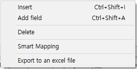 Map Editor – Menu
The following describes each menu.
Menu Description [Insert (Ctrl+Shift+I)]
Inserts an empty structure field of a new map before a selected structure field.
[Add field (Ctrl+Shift+A)]
Adds a structure field of a new map as a last field.
[Delete]
Delete a structure field of a selected map.
[Smart Mapping]
By comparing each structure field of the Source and Target columns, if compared fields' physical name and type are the same, the structure field of the map is automatically created. This is the auto map creation function.
[Export to an excel file]
Exports map resource data to an Excel file.
-
Mapping
There are following two methods for mapping.
Method Description Screen Split
Split the Map editor and then drag and drop a structure or message to move.
Smart Mapping
Compare each structure field of the Source and Target columns. If compared fields' physical name and type are the same, the structure field of the map is automatically created
The following describes how to split the Map editor vertically or horizontally.
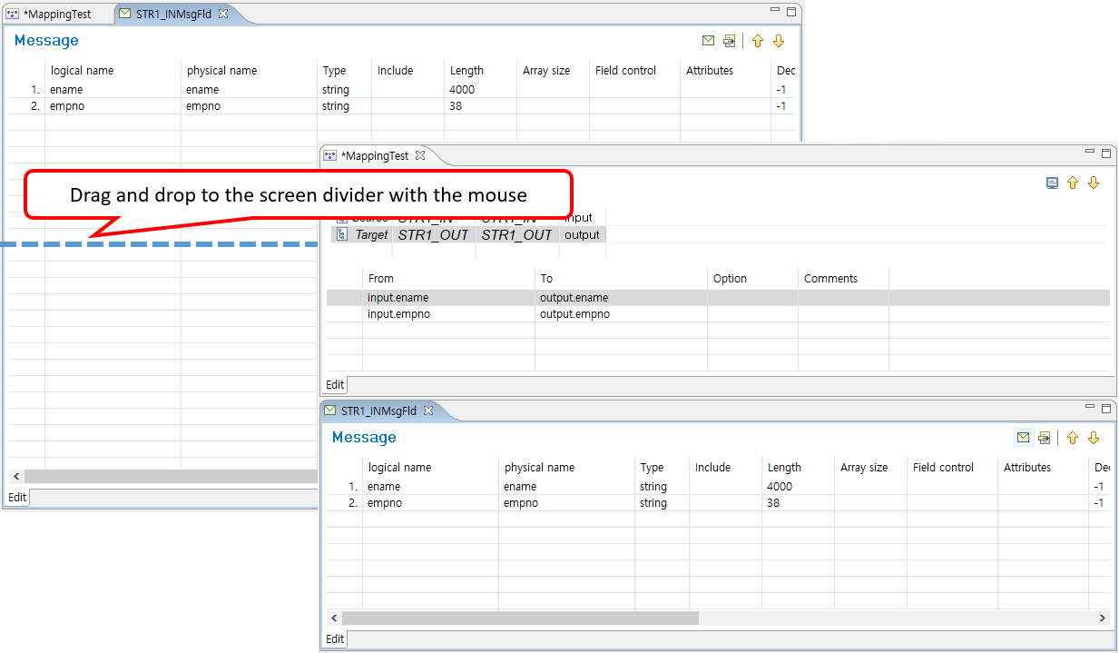 Map Editor – Screen Split
When vertically or horizontally splitting the Map editor to multiple script editing parts, click the tab title and drag and drop it to a desired location. At this time, check the dividing line where the screen is divided.
Select a field and drag and drop it to set mapping according to developer-specified Source and Target variables' aliases.
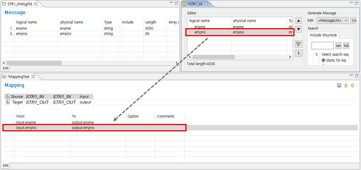 Map Editor – Field Mapping
The following describes Smart Mapping. Select [Smart Mapping] from the context menu of Map editor.
Selecting [Smart Mapping] automatically creates mapping items for fields with the same physical name and type. If there are no matched fields, nothing happens.
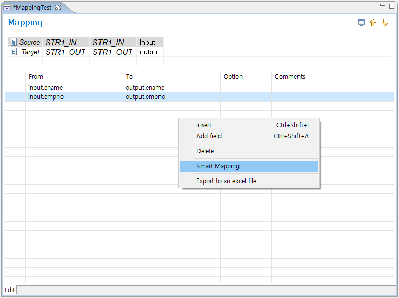 Map Editor – Smart Mapping Result
4. Source Generation, Compilation, and Dlupdate
ProMapper compilation is performed in three steps. The following describes the compilation process for each type of resources created in Studio from the functional point of view.
-
Source generation
Source is automatically created with ProMapper’s Source Generator for resources created in Studio. The created source is saved in resource storage of an integrated server.
-
Compilation
Created source is compiled, and ProMapper-related libraries are created.
-
Dlupdate
The created libraries can be used and updated in real time.
|
This guide does not describe about the PFM_SVC_EXT table because the table is customized for each project site. |
Source Generation
The following are files created for each resource type. For Workspace (WS) area resources, source files are created in a directory that ends with "_WS" such as "${PFMAPINCDIR_WS}". Files and functions processed in WS area are also created with a name that ends with "_WS".
-
Structure
Source File Location pfmMapper${Structure’s physical name}.h
${PMAPINCDIR}
pfmMapper${Structure’s physical name}.c
${PMAPSRCDIR}
-
Message
Source File Location pfmMapper${Message’s physical name}.h
${PMAPINCCDIR}
pfmMapper${Message’s physical name}.c
${PMAPSRCDIR}
-
Map
Source File Location pfmMapper${Map’s physical name}.c
${PMAPSRCDIR}
Compilation and Dlupdate
For ProMapper compilation, source generation and compilation are processed by selecting the [Compile Resource] menu in Studio and Dlupdate is processed by selecting the [Dlupdate] menu in Studio.
The following describes how to compile and execute Dlupdate on ProMapper resources.
-
Select a ProMapper resource to compile from Navigator. From the context menu, select the [Compile Resource] menu.
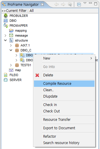 Compile Resource Menu
You can also select the resource and then press <Alt> + C or click the compilation icon. This works the same.
-
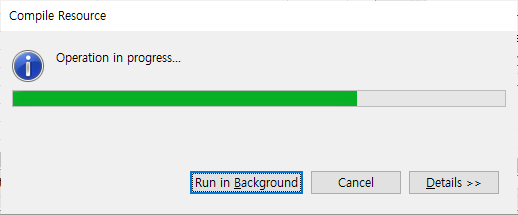
The following Compile Resource window is displayed. This window shows the compilation progress.
-
When the compilation is completed successfully, the compilation log is displayed in Console.
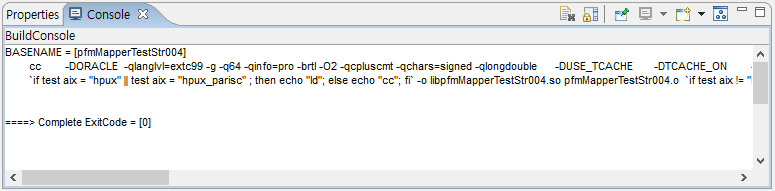 Compile Resource – Console
 -
Select and right-click the ProMapper resource. Select the [Dlupdate] menu.
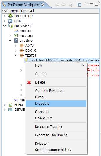 Dlupdate Menu
You can also select the resource and then press <Alt> + D or click the Dlupdate icon. This works the same.